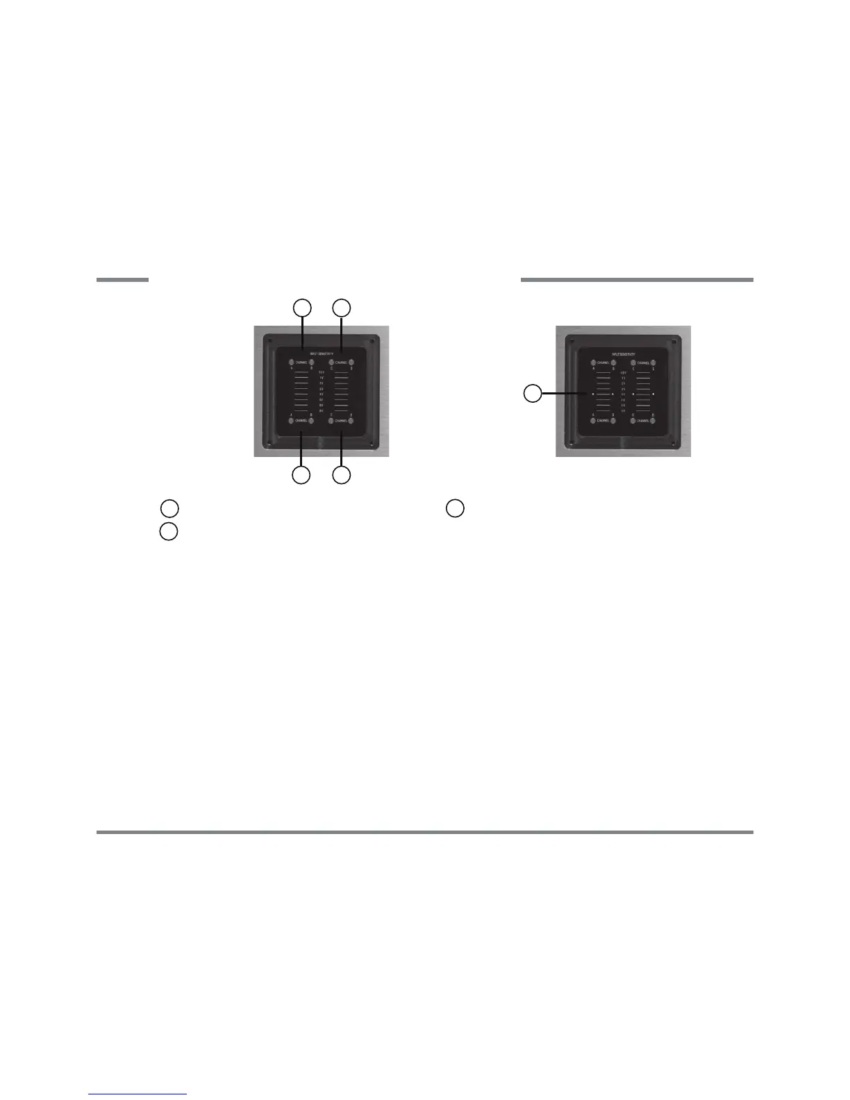
$GMXVWLQJWKHLQSXWVHQVLWLYLW\
7RDGMXVWWKHLQSXWVHQVLWLYLW\\RXKDYHWRUHPRYHWKHQDPHSODWHRQWRSRIWKHDPSOL¿HUZLWKWKHLQFOXGHGKH[DJRQVRFNHW
screw key. Under this plate are the pushbuttons for precise and easy adjustment of the input sensitivity. Each channel can
EHFRQ¿JXUHGVHSDUDWHO\7KH/('LQGLFDWRUVKRZVWKHDGMXVWHGLQSXWVHQVLWLYLW\RIHDFKFKDQQHO7KHFRQWUROVDUHQRYR-
OXPHFRQWUROVDQGDUHRQO\IRUVHWWLQJXSWKHLQSXWOHYHOVRIWKHDPSOL¿HUWRWKHRXWSXWOHYHOVRIWKHKHDGXQLWRUSUHDPSOL¿HU
1 Pushbutton for increasing the input sensitivity
With this control the input sensitivity of each channel can be increased stepwise.
2 Pushbutton for decreasing the input sensitivity
With this control the input sensitivity of each channel can be decreased stepwise.
/('LQGLFDWRUVKRZVWKHDGMXVWHGLQSXWVHQVLWLYLW\
The red shining LEDs indicate the adjusted input sensitivity. Please take care that the input sensitivity in bridged mode is
set up equally.
2 2
11
Pushbutton for increasing the input sensitivity
1
Pushbutton for decreasing the input sensitivity
2
3
LED-indicator shows the adjusted input sen-
sitivity
3
Fig. 1:
Control panel for
adjusting the input
sensitivity
Fig. 2:
Control panel with ad-
justed input sensitivity
to 4 Volts
ADJUSTING THE INPUT SENSITIVITY
28