10 of 52© 2021 BRAY INTERNATIONAL, INC. ALL RIGHTS RESERVED. BRAY.COM EN_TSM-2004-6A Advanced_Set-Up_20211012
SERIES 6A
ADVANCED SETUP GUIDE
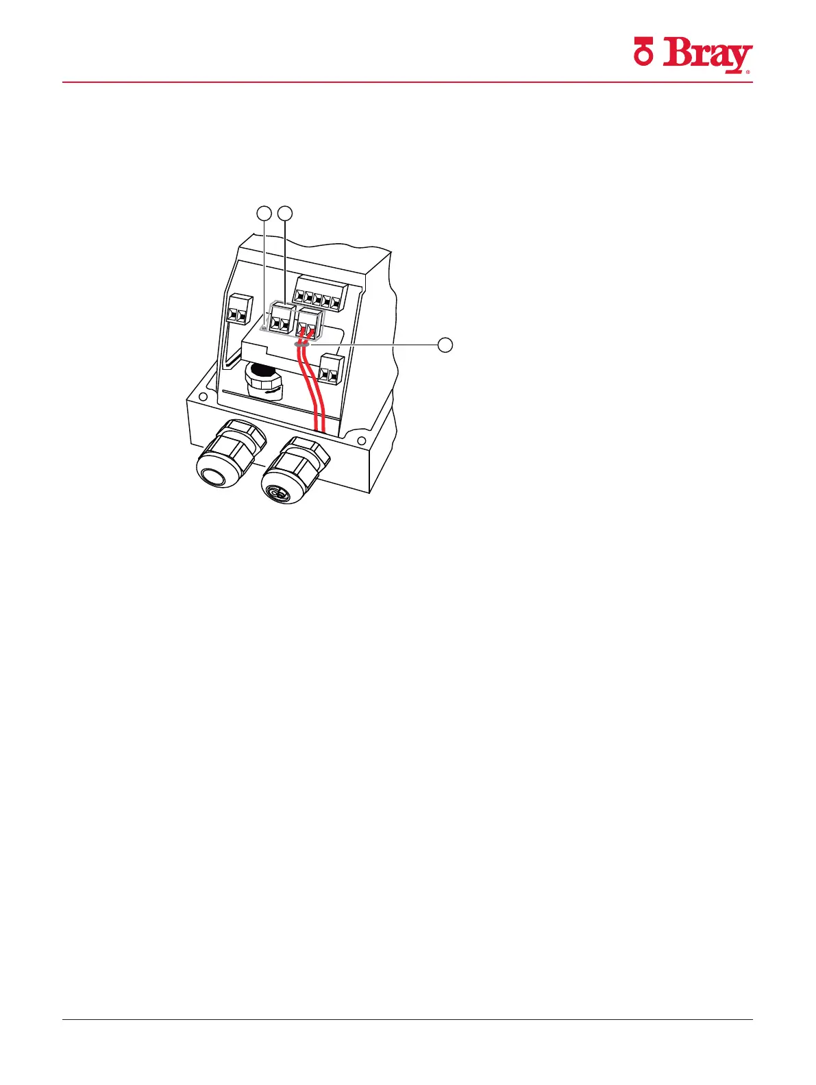
4. Slide the transparent cover ② up to the end stop of the basic electronics.
5. Tighten the screw ① of the transparent cover ②.
6. Connect the cables of each switch to the lug of the printed circuit board in pairs. Use the
provided cable ties ③ for this purpose.
① Screw
② Cover
③ Cable tie
Figure 5-11 Connecting the cables
Connection
5.2 Electrical wiring
SIPART PS2 with 4 to 20 mA/HART
84 Operating Instructions, 10/2020, A5E00074631-AF
Figure 14

 Loading...

