9 of 52© 2021 BRAY INTERNATIONAL, INC. ALL RIGHTS RESERVED. BRAY.COM EN_TSM-2004-6A Advanced_Set-Up_20211012
SERIES 6A
ADVANCED SETUP GUIDE
Figure 5-9 Inductive Limit Switches (ILS)
5.2.3.4 Mechanical Limit Switches (MLS) 6DR4004-6K / -8K
DANGER
Supply with hazardous voltage
If you connect the switching contacts of the 6DR4004-8K module to a hazardous voltage,
observe the following safety rules:
1. Isolate the device from power. Use a circuit breaker positioned near the device to do this.
2. Make sure that the device cannot be switched back on inadvertently.
3. Make sure the device is truly isolated from power.
CAUTION
Maximum AC/DC switching voltage with UL approval E344532
Mechanic Limit Switches (MLS) 6DR4004-6K/-8K
are approved for use with positioners with UL
approval. The maximum switching voltage in this case is ≤ 30 V AC/DC.
If switching voltages greater than 30 V are connected, the UL approval for the positioner
becomes invalid.
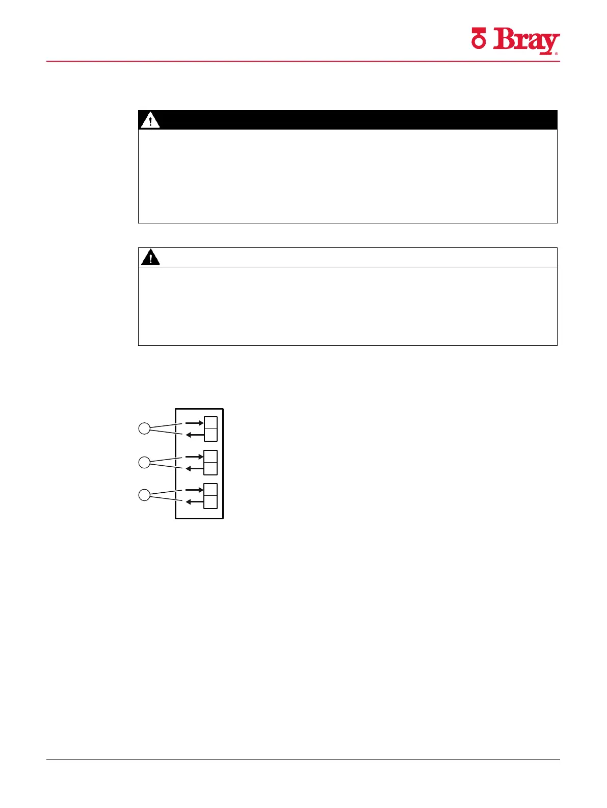
Connection diagram Mechanic Limit Switches (MLS) 6DR4004-6K and -8K
① Fault message output, has no function in combination with 6DR4004-4ES
② Digital output (limit monitor) A1
③ Digital output (limit monitor) A2
Figure 5-10 Mechanic Limit Switches (MLS)
Procedure
1. Loosen the screw ① on the transparent cover ②.
2. Pull the transparent cover ② up to the front end stop.
3. Tighten every cable in the corresponding terminal.
Connection
5.2 Electrical wiring
SIPART PS2 with 4 to 20 mA/HART
Operating Instructions, 10/2020, A5E00074631-AF 83
Figure 13

 Loading...

