8 of 52© 2021 BRAY INTERNATIONAL, INC. ALL RIGHTS RESERVED. BRAY.COM EN_TSM-2004-6A Advanced_Set-Up_20211012
SERIES 6A
ADVANCED SETUP GUIDE
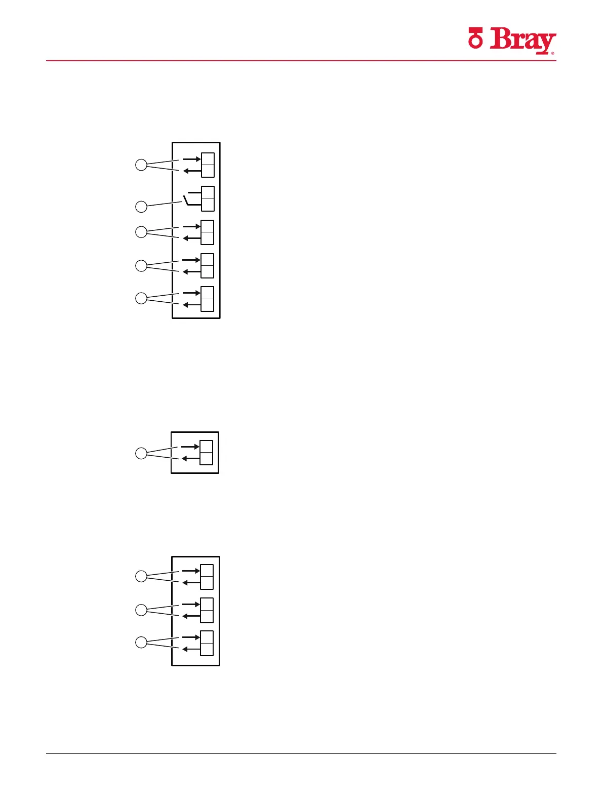
5.2.3.1 Digital I/O Module (DIO) 6DR4004-6A / -8A
① Digital input DI2, electrically isolated ④ Digital output DO1
② Digital input DI2, dry contact ⑤ Digital output DO2
③ Fault message output
Figure 10
Digital I/O Module (DIO)
5.2.3.2 Analog Output Module (AOM) 6DR4004-6J / -8J
① Analog output AO
Figure 11
Analog Output Module (AOM)
5.2.3.3 Inductive Limit Switches (ILS) 6DR4004-6G / -8G
① Fault message output, has no function in combination with 6DR4004-3ES
② Digital output (limit monitor) A1
③ Digital output (limit monitor) A2
Connection
5.2 Electrical wiring
SIPART PS2 with 4 to 20 mA/HART
82 Operating Instructions, 10/2020, A5E00074631-AF
Figure 12 Inductive Limit Switches (ILS)

 Loading...

