Bray Series 6P
Operation and Maintenance Manual
5
INPUT SIGNAL
PRESSURE
SUPPLY
OUT 2
OUT 1
2
1
6
3
4
15
7
8
9
10
11
12
13
14
5
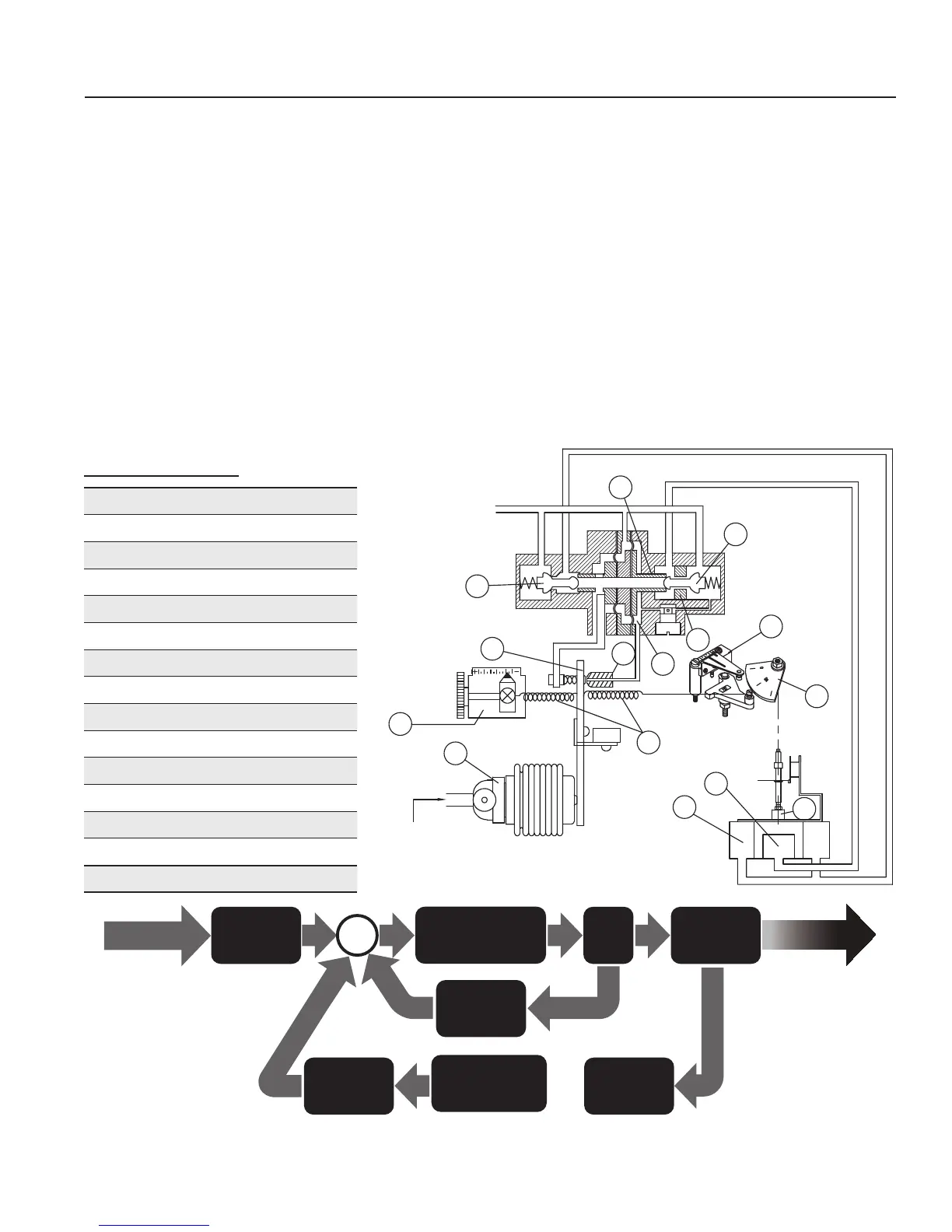
Operation Logic
• When signal input pressure increases, the bellows
(11)pushestheapper(13), the gap between the
nozzle (5) andtheapper(13) increases, which
causes pressure in the upper spool chamber (4) to
exhaust. This causes the spool (1) to shift right.
• As the spool (1) moves right, it pushes the poppet
(2) off its seat (3), and air pressure is supplied to
the center actuator chamber (9).
• At the same time, the spool (1) causes the left
poppet (14) to seat and vent the outer chambers
(10).
• As the actuator’s inner pressure increases, the
actuator stem (8) rotates.
• When the signal input pressure decreases, the
spool (1) moves to the left reversing the action,
lifting the left poppet (14) and supplying pressure
to the outer actuator chambers (10) and venting
the inner actuator chamber (9).
Bray Series 6P
1. Spool
2. Right Poppet
3. Seat
4. Spool Chamber
5. Nozzle
6. Span Adjustment
7. Cam
8. Actuator Stem
9. Inner Actuator Chamber
10. Outer Actuator Chamber
11. Bellows
12. Zero Adjustment
13. Flapper
14. Left Poppet
15. Feedback Springs
Input Signal
Bellows
Mechanism
Actuator
Pilot
Relay
Flapper & Nozzle
Mechanism
Stroke Output
Stabilizer
Spring
Communication
Mechanism
Feedback
Spring
Feedback
Lever
Figure 1

 Loading...