8
Battery Backup Unit (BBU) — Installation & Maintenance Manual Continued
1.0 Procedure
For assembly of a Bray Battery Backup Unit (BBU) to
a Bray S70 electronic actuator.
2.0 Tools Required
• Wire Strippers
• Wrench
• Allen Wrench
• Signal Generator
• Power Supply (100 VA Minimum Isolated Transformer)
• Screw Driver
3.0 Equipment
• Series 70 Actuator
• BBU
• Batteries (2)
• Wiring Diagram with applicable Wire Colors
• Mounting Hardware
• O-Rings
Installation
3.1 Wear safety glasses and all other appropriate safety equipment as directed by Bray HSE policies
before performing any of the listed tasks.
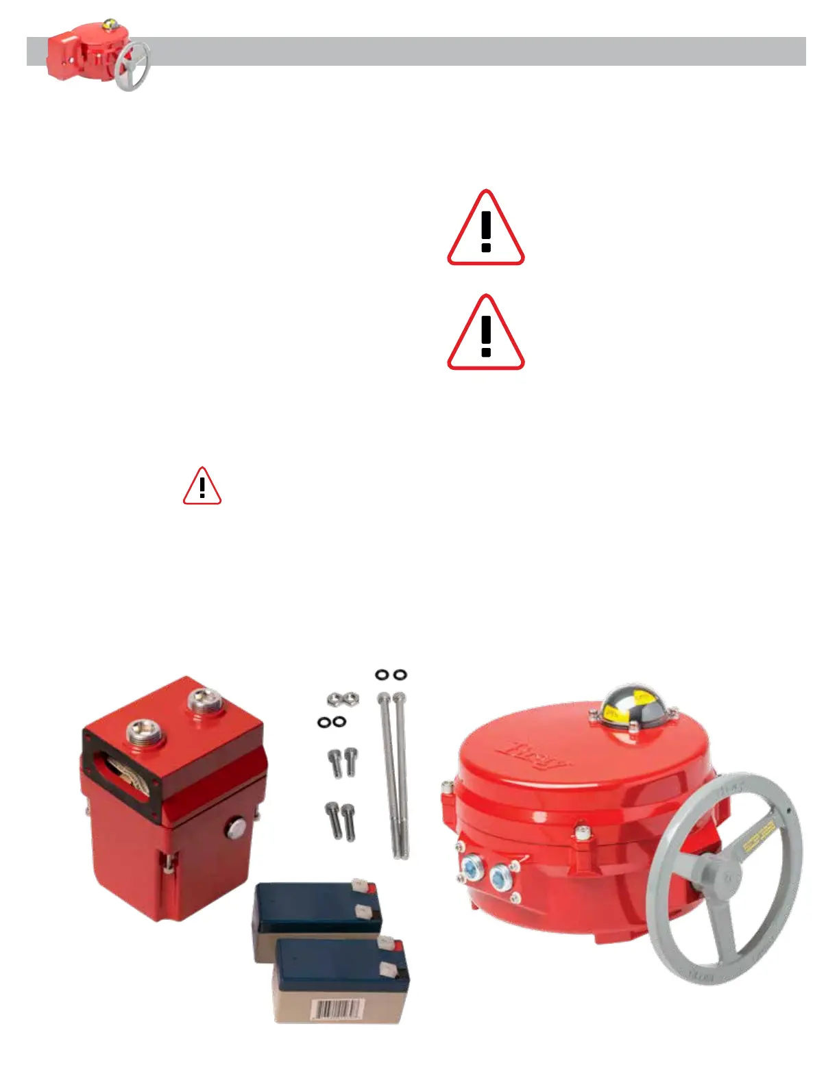
3.2 Retrieve all parts required to construct the S70/BBU assembly as specified on sales order's Traveler
BOM. Some hardware depicted below [Figure 1].
CAUTION: Risk of Property Damage.
Do not apply power to the system
before checking all wiring connec-
tions. Short circuited or improperly
connected wires may result in
permanent damage to the equipment.
IMPORTANT: Do not exceed the electrical ratings of the S70 Actuator or BBU.
CAUTION: Risk of Electric Shock. Discon-
nect the power supply before making
electrical connections to avoid electric
shock.
Figure 1
Actuator/BBU Preparation