3
FAN BR4951
The fan is intended for articial ventilation of the
room.
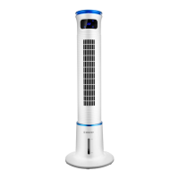
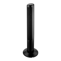
DESCRIPTION
1. Base
2. Water level scale
3. Body
4. Outgoing airow grid
5. Display
6. Control panel
7. Water tank lid/cool pack installation place
8. Detachable air inlet grid
9. Grid clamps
10. Carrying handle
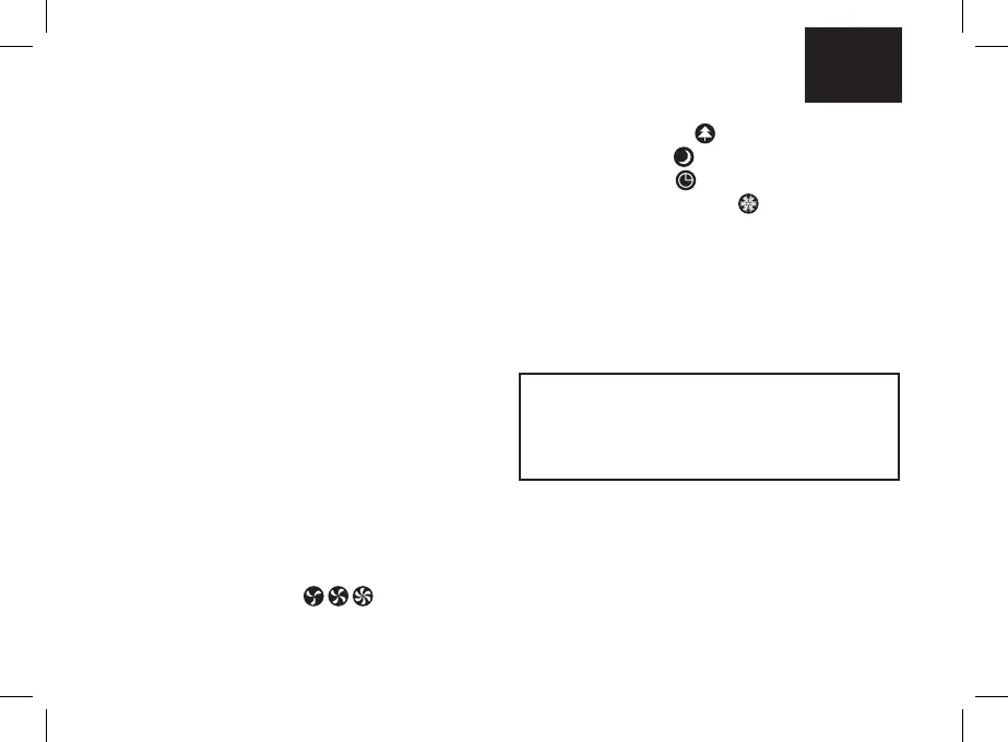
Control panel (6)
11. On/o button «ON/OFF»
12. Airow type selection button «WIND»
13. Fan body oscillation on/o button «OSC»
14. Cool shot on/o button «COOL»
15. Timer on/o button «Timer»
16. Airow speed selection button «SPEED»
Display (5)
17. Airow speed symbols «
, , »
18. Timer operation time/air temperature digits
EN
ATTENTION!
For additional protection it is reasonable to install a
residual current device (RCD) with nominal operation
current not exceeding 30 mA into the mains. To install
RCD, contact a specialist.
19. Airow type symbol « »
20. Night mode icon «
»
21. Timer on symbol «
»
22. Cool shot function symbol «
»
23. Remote control
24. On/o button «ON/OFF»
25. Airow speed selection button «SPEED»
26. Timer on/o button «Timer»
27. Cool shot on/o button «COOL»
28. Airow type selection button «WIND»
29. Fan body oscillation on/o button «Oscillator»
30. Battery holder