12
1 2 3 4 5 6 7 8
A
+VBATT INJ1- GAS INJ2- GAS INJ3- GAS INJ4- GAS COMINJPET-OUT COMINJPET-IN RPM-IN
B
GND-INJ INJ1PET-IN INJ2PET-IN INJ3PET-IN INJ4PET-IN LAMBDA-AIN MAP-AIN P1-AIN
C
GAS SV WATER TEMP. K-LINE SWITCH-LINE SENSPOWER LAMBDA-AOUT TGAS-AIN GNDBATT
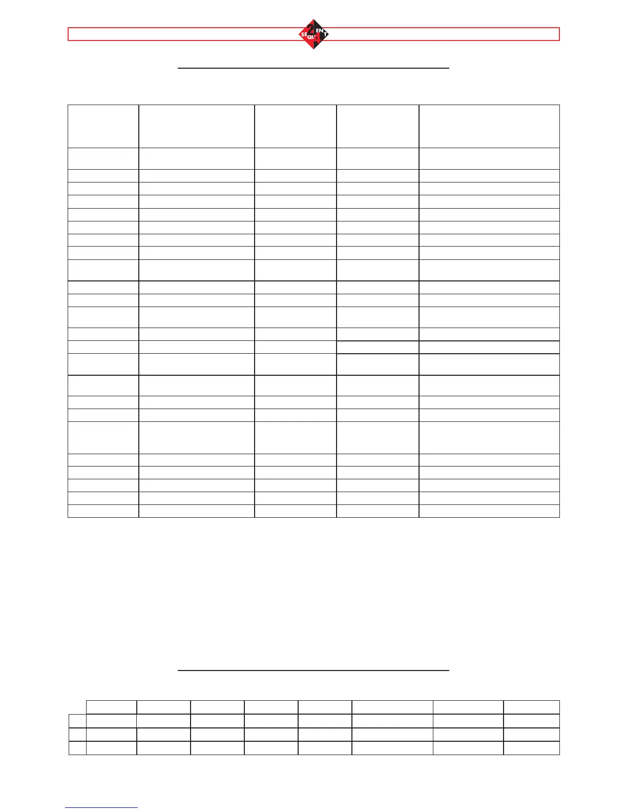
ANNEXES A
Pins
ANNEXES B
Location of the ECU pins
N. PIN OF
THE ECU
N. PIN OF THE
REMOTE
CONNECTOR
WIRE COLOUR WIRE NAME DESCRIPTION
A1 Note 1 Red +VBATT
ECU power supply from battery /
injectors current blow-by
B1 Ring Black GND-INJ Gas injectors ground
C1 1 Green/Black EVGAS Solenoid valve piloting outlet
A2 1 White/Green INJ1-GAS Gas injector 1 piloting outlet
B2 B1 Violet INJ1BENZ-IN Petrol injector 1 inlet
C2 2 Yellow TEMP.ACQUA Water temperature
A3 1 White/Green INJ2-GAS Gas injector 2 piloting outlet
B3 B2 Violet INJ2BENZ-IN Petrol injector 2 piloting intlet
C3 4 White LINEA-K
K line diagnostic
serial communication
A4 1 White/Green INJ3-GAS Gas injector 3 piloting outlet
B4 C1 Violet INJ3BENZ-IN Petrol injector 3 piloting intlet
C4 2 Green SWITCH LINE
Changeover switch
serial communication
A5 1 White/Green
INJ4-GAS Gas injector 4 piloting outlet
B5 C5 Violet
INJ4BENZ-IN Petrol injector 4 piloting intlet
C5 Note 2 Red SENSPOWER
5V power supply for sensors and
changeover switch
A6 A2 White/Brown COMINJPET-OUT
Petrol injectors common positive,
injectors side
B6 - Yellow LAMBDA-AIN Lambda oxygen sensor analog inlet
C6 Light blue LAMBDA-AOUT Lambda oxygen sensor analog outlet
A7 A1 White/Green COMINJPET-IN
Petrol injectors common positive,
petrol ECU side (or +V key)
B7 4 White MAP-AIN MAP analog inlet
C7 4 White TGAS-AIN Temperature analog inlet
A8 - Grey RPM-IN RPM inlet
B8 2 Green P1-AIN Gas pressure analog inlet
C8 Note 3 Black GNDBATT ECU and sensors ground
Note 1: The A1 pin of the ECU (battery positive) is connected with the pin 3 of the connector for the communication with the
PC.
Note 2: The C5 pin of the ECU (sensors positive) is connected with the following pins of the remote connectors:
• Pin 3 of the gas pressure and temperature sensor
• Pin 4 of the changeover switch
• Pin 2 of the MAP sensor
Note 3: The C8 pin of the ECU (ECU and sensors ground) is connected with the following pins of the remote connectors:
• Pin 1 of the gas pressure and temperature sensor
• Pin 3 of the changeover switch
• Pin 1 of the MAP sensor
• Pin 1 of the engine coolant temperature sensor
• Pin 1 of the gas level sensor