


R
Raymond MolinaAug 18, 2025
Why is my Breas Clearway 2 very noisy during treatment?
- TTammy GallowayAug 18, 2025
The blower may be faulty and needs to be replaced.
Why is my Breas Clearway 2 very noisy during treatment?
The blower may be faulty and needs to be replaced.
What to do if my Breas Medical Equipment is showing a pressure fault (mismatch)?
Check the pressure tubes to ensure they are properly connected and not kinked. If the tubes are fine, the pressure transducer may be faulty, requiring replacement of the power PCB.
Why is my Breas Clearway 2 very noisy in standby?
The cooling fan may be faulty and needs replacing.
Why is the maximum pressure not reached on my Breas Medical Equipment?
Check the calibration. Also, inspect the internal airpath for leaks. The valve or blower may be faulty and require inspection. It is also possible that the power PCB is faulty and needs replacing.
What to do if my Breas Medical Equipment Clearway 2 does not switch on when connected to AC mains, and the AC LED is not lit?
First, verify the mains supply to ensure there is power at the socket. If the socket is functional, check the fuse in the mains cable plug. If problems persist, there may be a faulty power supply, in which case you should verify the PSU DC output and replace the PSU if it is faulty. A faulty Power PCB could also be the reason, so it should be replaced if necessary.
What to do if my Breas Medical Equipment battery will not charge?
If the battery isn't charging, the battery may be faulty and needs replacing. Alternatively, the Power PCB may be faulty and also needs replacing.
What to do if my Breas Medical Equipment Clearway 2 does not switch on when connected to AC mains, but the AC LED is lit?
Check the front panel connection to the display PCB. If the connection is secure, the front panel may be faulty and require replacement, along with the display command PCB. Also, the Power PCB could be faulty, and replacing it might solve the problem.
What to do if my Breas Clearway 2 Medical Equipment blower does not run during treatment, resulting in no airflow?
Check the blower connector and cables to ensure they are properly connected. If the connections are good, the blower itself may be faulty and require replacement. A faulty Power PCB could also be the cause and may need replacing.
What to do if my Breas Medical Equipment Clearway 2 does not switch on when running on battery power?
Check the battery cables to ensure they are properly connected. If the cables are secure, verify that the battery is charged. If the issue persists, the Power PCB may be faulty and require replacement.
What to do if my Breas Clearway 2 manual switch is not working?
Check the function with both the front and remote switch. Also, check the switch connection CON 2 on the display PCB. If those don't work, replace the switch.
Contact details for Breas Medical Ltd, including address, phone, and email.
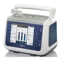
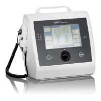
Overview of the Clearway 2 device and its therapeutic options.
Purpose of the Clearway 2 airway clearance device for patients.
Requirements for service personnel working with the Clearway 2.
Guidance on how to use the service manual effectively.
Explanation of icons used throughout the service manual.
Objective of carrying out regular inspection and preventative maintenance.
Preliminary steps and safety precautions before maintenance.
Recommended intervals and procedures for device inspection and maintenance.
Lists required equipment and tools for inspection and component replacement.
Identifies parts needed for service and their required replacement intervals.
Steps for preparing the device for inspection, including cleaning and record keeping.
Procedures for visually inspecting the exterior of the Clearway 2 device.
Steps for performing pressure and flow tests on the Clearway 2.
Detailed steps for internal inspection, including cleaning and checking fastenings.
Guidelines and recommendations for performing electrical safety tests on the device.
Overview of the service menu functions, including date/time and calibration.
Procedure for setting the device's internal clock and date for accurate logging.
Steps for performing pressure and flow calibration using the service menu.
Information available on diagnostic screens for analyzing machine functions.
Details on how the alarm log displays event descriptions and occurrences.
Procedure for restoring device settings to their factory defaults.
Identification of internal components within the front case of the Clearway 2.
Labelled diagram of the Display Printed Circuit Board and its connectors.
Identification of internal components located within the rear case of the Clearway 2.
Labelled diagram of the Power Printed Circuit Board and its connectors.
System block diagram illustrating the overall architecture of the Clearway 2.
Block diagram detailing the functionality of the Control PCB.
Block diagram detailing the functionality of the Display PCB.
Diagrams illustrating the inspiratory and expiratory stages of the pneumatic system.
Step-by-step guide for safely removing and replacing the internal battery.
Instructions for safely opening and reassembling the Clearway 2 device case.
Procedure for removing and replacing the Power Control PCB.
Procedure for removing and replacing the Communications PCB.
Procedure for removing and replacing the Display Command PCB.
Step-by-step guide for removing and replacing the blower unit.
Instructions for removing, cleaning, and replacing the valve assembly.
Procedure for removing and replacing the internal power supply unit.
Guide for removing and replacing the flow transducer component.
Recommended procedure for replacing the device's clock battery.
Detailed instructions for replacing the alarm battery, including soldering.
Description of the Power Control PCB's functions and components.
Description of the Display Command PCB's functions and components.
Description of the Communication PCB's interfaces and processor.
Information on monitoring battery status, charging, and storage recommendations.
Details on the 3V Lithium coin cell for the internal clock.
Information on the 3.6V NiMH rechargeable battery for alarms.
Troubleshoots device not switching on due to power or connection problems.
Addresses issues where the device fails to achieve target pressures.
Identifies causes and solutions for abnormal noise during operation.
Diagnoses and resolves discrepancies in pressure readings.
Troubleshoots problems related to the device's battery not charging.
Solutions for device overheating and high temperature warnings.
Resolves issues where the device does not recognize the SD card.
Troubleshoots problems with the SpO2 sensor connection or function.
Information on the device's compliance with EMC standards.
Guidelines for returning products to Breas for service or repair.
A template for recording patient-specific device settings.
A template for documenting inspection results and observations.
List of optional accessories available for the Clearway 2.
| Display | LCD |
|---|---|
| Input Power | 100-240 VAC, 50/60 Hz |
| Inspiratory Pressure Range | 4-30 cmH2O |
| Expiratory Pressure Range | 4-20 cmH2O |
| Inspiratory Time Range | 0.3-3.0 seconds |
| Noise Level | < 30 dBA at 10 cmH2O |
| Operating Temperature | +5°C to +40°C |
| Humidity Range | 15-95% (non-condensing) |