13
Chapter 1: Hardware insertion.
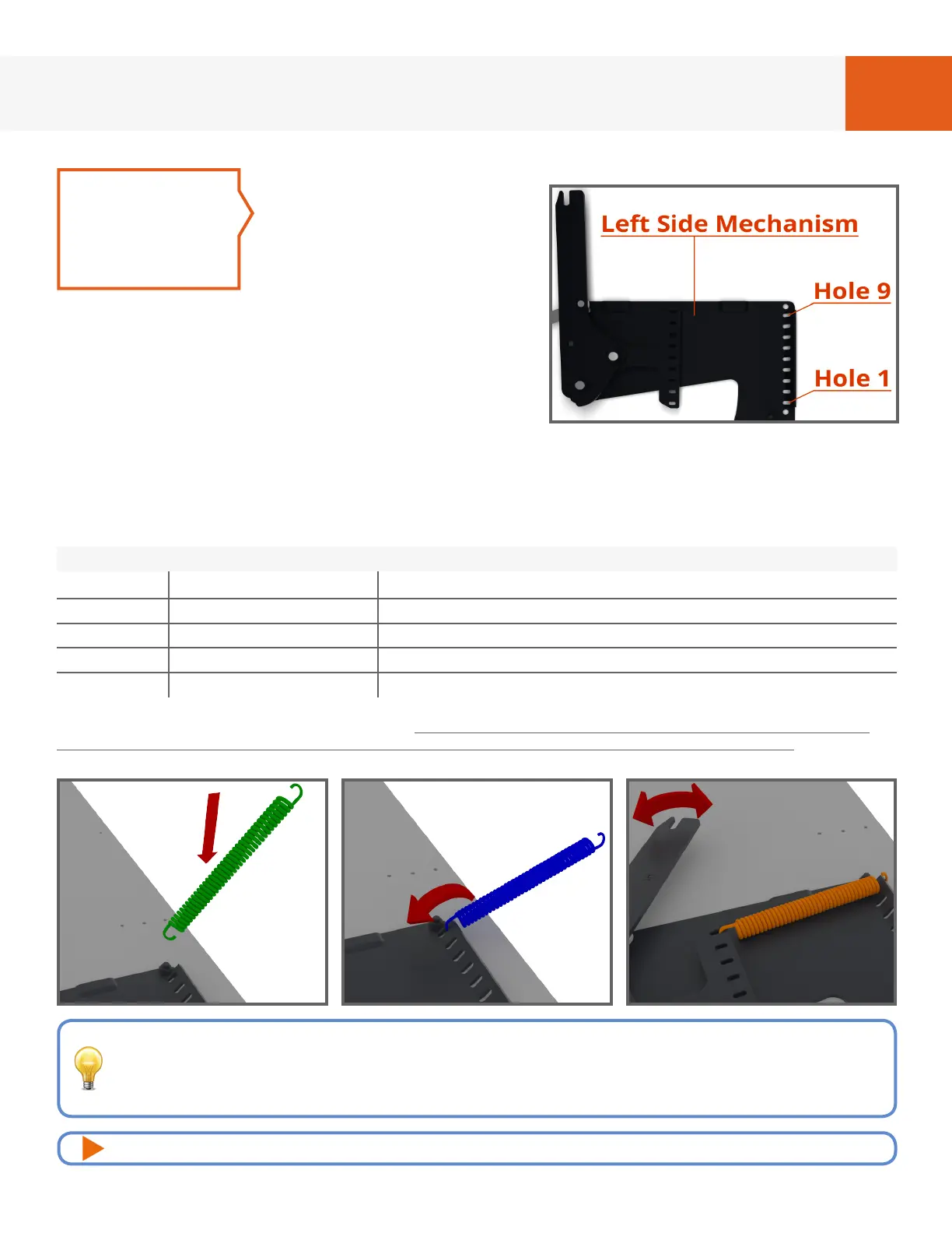
There are 9 Spring
locations. Referring to the
spring application chart
and Fig. 1E-1H, insert
springs into the hole
numbers noted for the
amount of springs you will be using. Position
the spring with the open side of the hook
facing down as shown in green. Hook that side
into the stationary portion of the mechanism
and rotate the spring 180° as shown in blue.
Hook the opposite side into the corresponding
hole on the movable portion of the mechanism as shown in orange. You’ll need
to rotate the mechanism arm as you go to keep tension on the springs you’ve
inserted and to create the proper spacing for the spring you’re working on. Start
with the higher quantity of springs listed for your bed size, you may have to add or
remove springs depending on the weight of your mattress.
STEP 5
FIG. 1E
FIG. 1F FIG. 1G FIG. 1H
We recommend you start adding springs toward to the top of the mechanism rst
(at or near hole #9) and work your way down, adjusting the mechanism arm as
you go to keep tension on the existing springs. Once nished, add a piece of
masking tape to keep the springs from falling out of place.
For video instructions of this specic step, visit: breda.us/springs
*Please note: These are recommendations only, the actual quantity needed will vary depending on the
weight of the mattress including all bedding. We recommend starting with the higher quantity springs
shown in the table for your bed size. Adjustment will be done later at the end of this booklet.
Spring Application Chart
Bed Size Spring Quantity
Hole Numbers (Referring to Fig. 2A)
Twin 2 or 3 spring per side Holes 4 through 5 (2 springs) OR Holes 4 through 6 (3 springs)
Twin X-Long 2 or 3 spring per side Holes 4 through 5 (2 springs) OR Holes 4 through 6 (3 springs)
Full 3 or 5 spring per side Holes 4 through 6 (3 springs) OR Holes 3 through 7 (5 springs)
Queen 5 or 6 spring per side Holes 3 through 7 (5 springs) OR Holes 2 through 7 (6 springs)