BREN-TRONICS, INC.
10 Brayton Court
Commack, NY 11725
P: 631-499-5155 | F: 631-499-5504
www.bren-tronics.com
Page 14 of 25
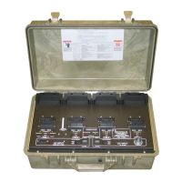
ALT 170C
(BTC-70844-2)
PR4G WORKSHOP CHARGER
OPERATION MANUAL
850084 REV D
Data presented in this document is subject to change without notice
2-2 PRELIMINARY SETUP PROCEDURES
Step 1. Place the unit on the work surface. Unscrew the pressure equalization valve
(near the carrying handle) in a counterclockwise direction about two full
turns. Unfasten latches and open cover.
Step 2. Set AC and DC power ON-OFF switches, to OFF position.
Step 3. The Cover may be removed by removing both hinge pins with pliers.
Step 4. For AC operation: Connect AC power cord from AC INPUT connector to
power source and set AC power ON-OFF switch to ON position. Observe
that POWER ON LED lights, fan operates, and all LED status indicators
blink in order (amber, green, then red) briefly when power is first applied.
Step 5. For DC operation: Connect DC cable from 24 VOLT DC INPUT connector
to DC power source (via NATO slave receptacle found in most military
vehicles) and set DC power ON-OFF switch ON position. Observe that
POWER ON LED lights, fan operates, and all LED status indicators blink in
order (amber, green, then red) briefly when power is first applied. Note that
if both AC and DC power are connected that DC power will be used if the
DC power switch is on.
Step 6. Observe that only the POWER ON LED is lit.
Step 7. Install appropriate battery adapter(s) on panel for battery types to be
charged. Install the Adapter(s) by placing the back of the adapter into the
rear retainer and rotating the adapter down until the front retainer clicks over
it. Note the alignment of the pins. The connector can only plug in one way.
Do not force it. Be sure that battery adapter and connector are fully seated.
All battery adapters are interchangeable, only the battery connections are
different.
Step 8. Observe, after a short delay, the amber CHARGE LED’s blink for several
seconds at each installed adapter. This shows battery charger circuits are
initialized to the selected battery adapter and are ready to accept a battery
(or batteries) for charging. If all of the Indicators for a channel light at the
same time, the Adapter could not be recognized or the adapter is damaged.
Insure it is seated correctly.