10
1
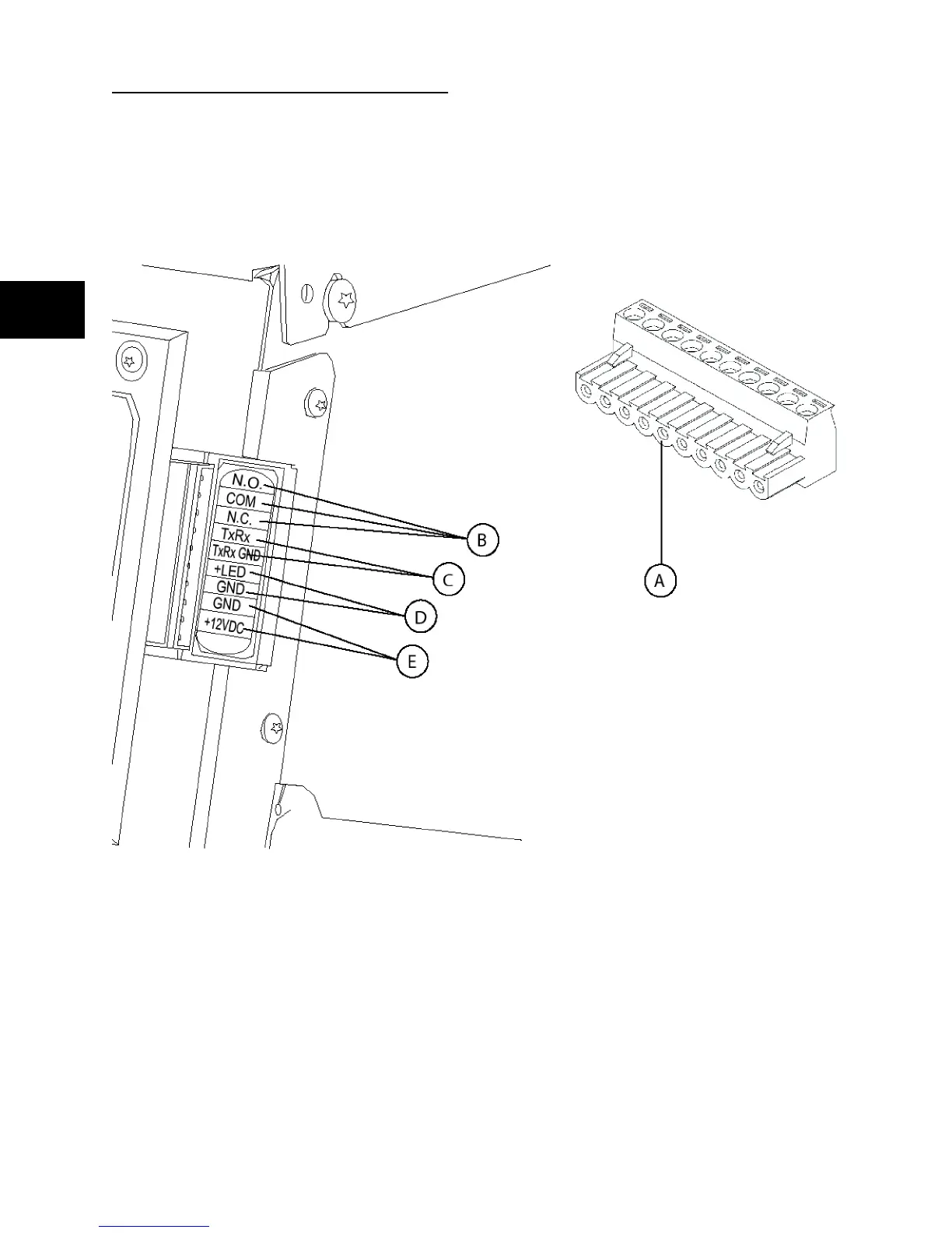
SYSTEM CONNECTION
Low Voltage (LV) connections to signal fault contacts, transfer switch communications, remote LED and
auxiliary 12VDC power are made to a removable ten-pin connector plug. Compare this illustration with the
location of these important connections:
A - 10 Pole Connector Plug
B - Fault Contacts — Use NO, COM and NC for operating a siren, light, optional GenAlert, etc. to alert
you in case of a fault. Contacts reverse state (NO goes to NC and vice versa) upon a fault condition.
C - Transfer Switch Communication — Connects to transfer switch control board for communication
interface.
D - Remote LED Output — Used to connect to the remote LED supplied with the generator. The remote
LED will turn on and off in a series of blinks if certain faults are detected in the generator.
E - +12Volt DC, .5 Amp Output — Internal auxiliary power supply.
 Loading...