36
2
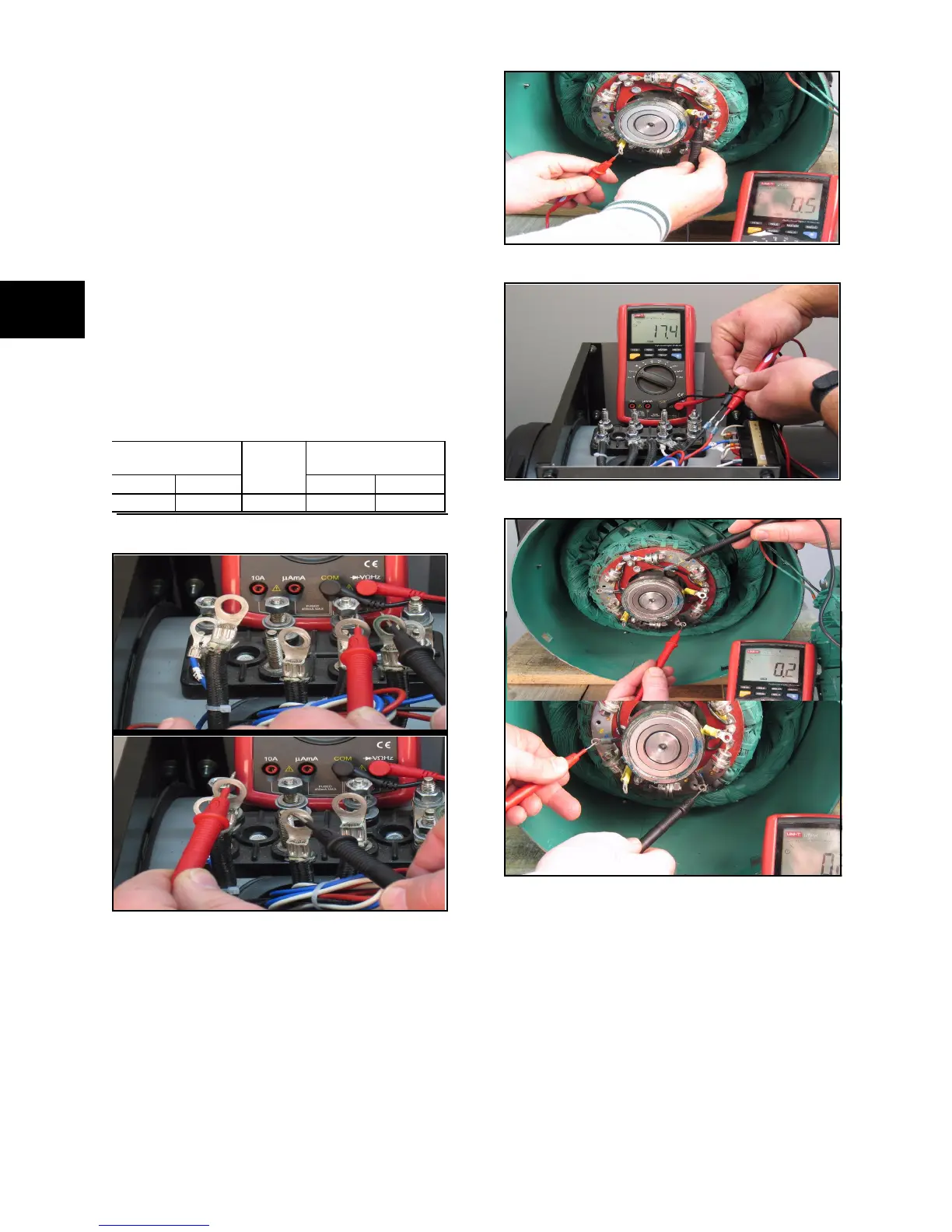
TEST 5 - Test Alternator Windings
There are four components that contain windings
that form an electrical path of low resistance.
Each component can be checked for continuity.
To Check Winding for Continuity:
1. Using meter, measure the loop resistance
of the following four components:
• Exciter Stator
• Exciter Rotor
• Main Stator
• Main Rotor
2. Verify measured values against those
listed in the table below.
NOTE: These very small resistances require
precision test equipment to obtain accurate
measurements. However, a standard meter will
provide a good indication of winding continuity.
Figure 27 Generator Stator Resistance
Figure 28 Generator Rotor Resistance
Figure 29 Exciter Stator Resistance
Figure 30 Exciter Rotor Resistance
• If winding resistance is
acceptable,proceed to Insulation
Resistance Test.
• If winding resistance is not acceptable,
repair or replace as necessary.
Generator Resistance Exciter Resistance
Stator Rotor
Exciter
Field No
Load Volts
Stator Rotor
0.07 0.46 10.1 18.0 0.120
 Loading...