Do you have a question about the Briggs & Stratton 276535 and is the answer not in the manual?
Briggs & Stratton engine usage guidelines and warnings regarding unauthorized applications and competitive events.
Explanation of DANGER, WARNING, CAUTION signal words and the safety alert symbol for hazard identification.
Essential safety practices including reading manual, eye protection, preventing accidental starting, and engine maintenance.
Visual representations of hazards such as explosion, fire, shock, chemical burns, and entanglement.
Warnings about gasoline's flammability, explosion risks, and safe fueling procedures.
Hazards associated with unintentional sparking, leading to fire, shock, or entanglement.
Dangers of carbon monoxide gas from engine exhaust, requiring outdoor operation.
Dangers of rotating parts causing entanglement, amputation, or severe lacerations, and safe operation guidelines.
Risks of broken bones and ensuring external equipment components are securely attached before starting.
Explanation of the two-cycle engine's crankcase induction, porting, and combustion process.
Description of the breakerless ignition system using electronic components instead of mechanical points.
Explanation of the rewind starter mechanism involving retainer, friction disc, and engagement dogs.
Overview of the 120VDC electric start system, including pinion gear engagement.
Recommended maintenance tasks for 25 and 50-hour intervals, including spark plug and exhaust port checks.
Procedure for replacing the spark plug, including gap setting and torque specifications.
Steps for cleaning the exhaust system, including muffler removal and exhaust port carbon scraping.
Categorization of common engine operation complaints like no start, hard starting, and vibration.
Systematic troubleshooting approach for ignition, carburetion, and compression issues.
Procedure for checking the ignition system's spark output using a tester.
Troubleshooting engine misfires and checking carburetion for wet or dry spark plugs and fuel delivery.
Procedure for checking engine compression using a tester and identifying potential causes for low compression.
Identifying how powered equipment issues can mimic engine malfunctions, requiring equipment checks.
Diagnosing hard starting, kickback, or no-start conditions and causes of engine vibration.
Troubleshooting power loss and diagnosing starter motor failures to turn the engine.
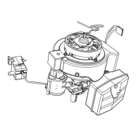
Instructions for removing the engine shroud, including disconnecting the spark plug wire and removing fasteners.
Procedure for removing the carburetor, including fuel line disconnection and primer tube removal.
Steps to remove the flywheel, including nut removal, and using a mallet for separation.
Procedure for removing the optional 120V electric starter assembly.
Instructions for removing the muffler by unscrewing mounting bolts and discarding the gasket.
Procedure for removing the ignition module by unscrewing the mounting bolts.
Steps for separating crankcase halves, removing crankshaft assembly, and discarding oil seals.
Removing the piston and rod assembly, including connecting rod cap and wrist pin.
Procedure for removing the cylinder head, including loosening studs and nuts and discarding the gasket.
Checking the flywheel key and keyway for damage, shearing, or distortion.
Inspecting ball bearings for wear and the crankcase for cracks and cleaning surfaces.
Measuring the cylinder bore for wear using gauges and calipers.
Procedure for installing piston rings, checking end gap, side clearance, and piston wear.
Checking the piston pin diameter and inspecting the connecting rod for wear or damage.
Procedure for disassembling the carburetor, including throttle plate, choke plate, and bowl removal.
Steps for removing the pilot jet, fuel filter screen, float hinge pin, and needle valve assembly.
Steps for cleaning and inspecting all carburetor parts, flushing passages, and drying.
Procedure for assembling the carburetor, including installing jets, nozzle, and pilot jet.
Installing the brass inlet seat, needle valve, float assembly, and adjusting float height.
Installing the throttle shaft, throttle plate, choke shaft, and choke plate into the carburetor.
Procedure for replacing the rewind starter assembly and its rope.
Steps for removing and installing the optional electric starter motor and associated switch.
Lubricating and assembling the piston pin into the piston and connecting rod.
Instructions for installing piston rings onto the piston, noting model-specific configurations.
Lubricating and installing the piston and connecting rod assembly into the cylinder bore.
Installing connecting rod and rod cap liners, ensuring proper seating and alignment.
Placing the crankshaft into the cylinder and assembling the connecting rod to the crankpin.
Torqueing the connecting rod screws to the specified value to secure the assembly.
Procedure for installing oil seals onto the crankshaft, ensuring proper centering and alignment.
Assembling the crankcase cover using appropriate sealant and torqueing screws.
Installing the cylinder head with a new gasket and torqueing head bolts.
Assembling the flywheel key, ignition coil, and flywheel, ensuring proper alignment and torque.
Installing the air vane governor bracket, link, and air vane, checking for free movement.
Installing the intake manifold and carburetor with new gaskets and torqueing fasteners.
Checking governor operation by measuring air vane to cylinder distance and adjusting linkage.
Installing the muffler with a new gasket and torqueing mounting screws.
Installing the blower housing, ensuring proper routing of ground wire and torqueing fasteners.
Adjusting the governor by bending the bracket where the governor spring is attached.
List of fasteners with their required wrench/socket size and torque values.
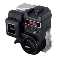
Key engine specifications including bore, stroke, displacement, and governed top speed.
Detailed standard and reject dimensions for cylinder bore, crankshaft, piston, and piston rings.
| Fuel Type | Gasoline |
|---|---|
| Starting System | Recoil |
| Carburetor | Float Feed |
| Governor System | Mechanical |
| Lubrication System | Splash |
| Air Cleaner | Dual Element |
| Shaft Orientation | Horizontal |
| Rotation | Counterclockwise |