4 BRIGGSandSTRATTON.COM
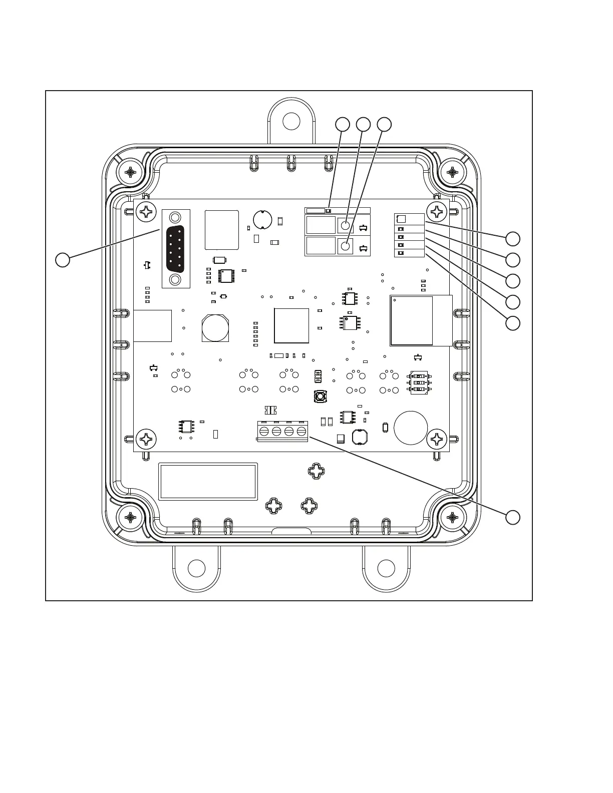
A • Power Indicator LED
B • WiFi Configuration button
C • Device Configuration button
D • Mode LED
E • WiFi Indicator LED
F • RS-485 Indicator LED
G • Device Indicator LED
H • CPU Indicator LED
J • Input Terminal Block (Field Connections)
K • Service port (serial)
The wireless module can be installed wherever it is convenient and a good wireless signal is present, either an indoor or outdoor
location. The
wireless gateway module
must be accessible for service. Discuss layout suggestions / changes with the owner before
beginning the system installation process.
VIN+ D+ D- GND
Power
WiFi
Mode
RS-485
Device
CPU
WiFi
Config
Device
Config
E
D
F
G
H
K
A B C
J
Figure 1
 Loading...