6 BRIGGSandSTRATTON.COM
Installation
It is recommended to use an 18AWG double-twisted shielded pair
wire to connect the
wireless gateway module
to the generator.
This wire is available from Briggs and Stratton™. For more
information please visit our website at
www.briggsandstratton.com
.
Mounting Guidelines
The power management modules are contained in a NEMA Type
4 enclosure. The wireless gateway module components are
contained in a NEMA Type 3R enclosure that is suitable for indoor/
outdoor use. The guidelines for mounting the enclosure include:
• Install enclosure on a firm, sturdy supporting structure.
• The enclosure must be accessible for service.
• NEVER install the device where any corrosive substance
might drip onto the enclosure.
• Protect the device at all times against excessive moisture,
dust, dirt, lint, construction grit and corrosive vapors.
• Install an enclosure to maximize wireless performance. Avoid
mounting the enclosure inside confined metal spaces. When
possible, mount enclosure in open area.
• The enclosure must be mounted vertically so that the grommet
(A, Figure 4 ) is on the bottom to prevent water from entering
the enclosure.
Figure 4
Disconnect the Power
Before performing any installation, maintenance, or service
on the generator, ALWAYS perform the following steps:
1. Set generator system switch to OFF
2. Set generator circuit breaker to OFF.
3. Remove the fuse from the main generator.
4. Utility voltage is present at generator control
panel. Remove the fuses from the transfer switch to
disconnect power before servicing the control panel.
5. Disconnect negative battery cable from negative
battery terminal, indicated by NEGATIVE, NEG, or (-).
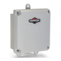
Connect the Wires
Remove the cover (A, Figure 5) from the
wireless gateway
module
by loosening the screws (B) DO NOT remove the rubber
grommet (C) from the hole in the bottom of the box.
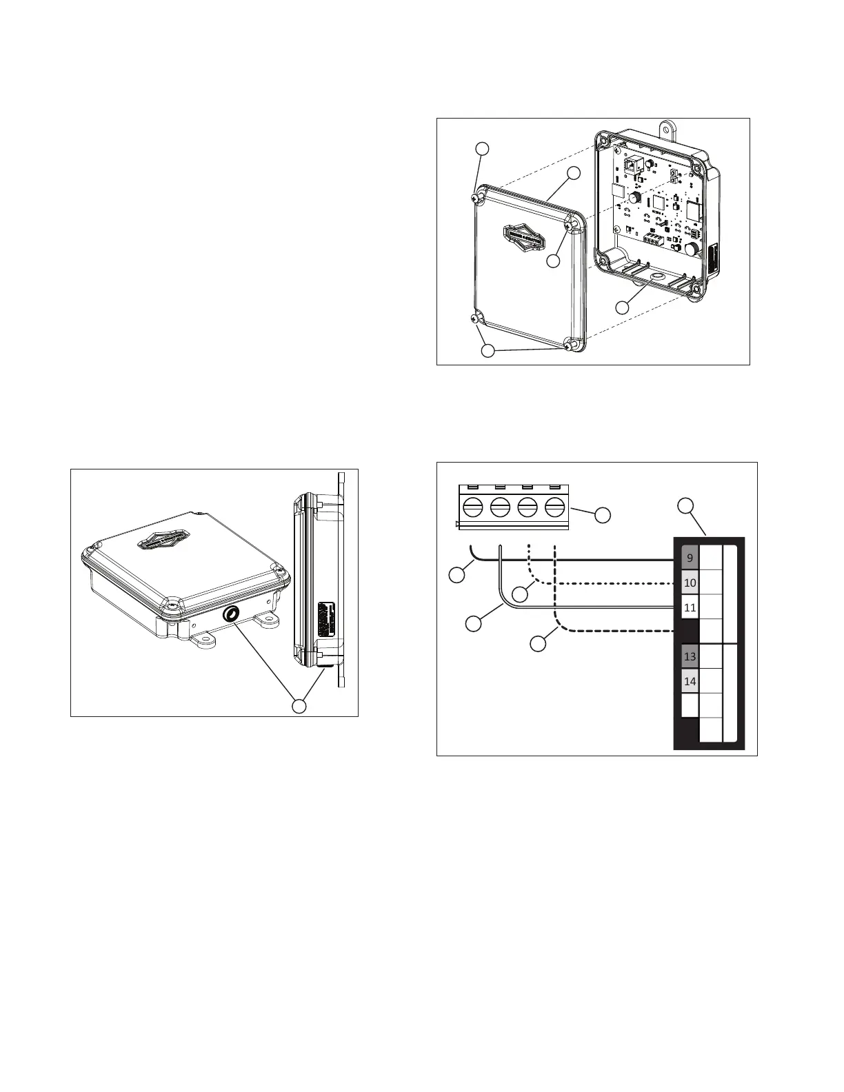
Figure 5
Wire the wireless gateway module inputs (A, Figure 6) to
the “WiFi” field wiring terminal blocks
of the generator (B). The
wireless gateway module
terminal block connections and the
generator terminal block connections must be torqued to 0.5 Nm
(4.4 in-lb).
Figure 6
VIN+ D+ D- GND
12
15
16
(B)
+12V
(A)
GND
+12V
(B)
(A)
GND
W
I
F
I
C
E
L
L
U
L
A
R
A
B
C
D
E
F
1. Connect the red wire (C, Figure 6) to the “WiFi +12V”
terminal on the generator and the “VIN(+)” terminal on
the wireless gateway module.
2. Connect the black wire (F, Figure 6) to the
“WiFi GND” terminal on the generator and the “GND”
terminal on the wireless gateway module.
3. Connect the white wire (D, Figure 6) to the “WiFi A”
terminal on the generator and the “D+” terminal on the
wireless gateway module.
4. Connect the orange wire (E, Figure 6) to the “WiFi B”
terminal on the generator and the “D-” terminal on the
wireless gateway module.
5. Connect the shield wire (if present) from the cable
to either the GND terminal on the wireless gateway
module or the “WiFi GND” on the generator, NOT both.
 Loading...