!
©Copyright!! !EN-V2016!
The!information!in!this!document!is!subject!to!change!without!notice! 25!
!
!
4 Installation!
This!controller!includes!a!front!display,!a!central!control!key!and!a!side!button.!
The!controller!must!be!set!up!vertically,!on!a!plane!surface,!keeping!at!least!15cm!from!the! wall!and!
from!other!co m p on e nts!to !en su re!p rop er!v en tilation .!
Make!sure!that!all!the!hydraulic!circuits!are!shut!and!that!the!power!supply!is!isolated!before!beginn ing!
installation .!
!
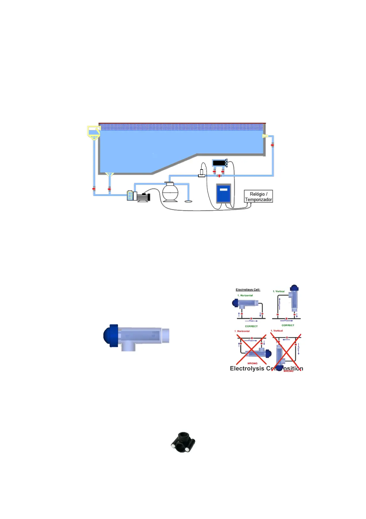
4.1 Hydraulic!Installation!
!
Fig!3-!Hydraulic System Scheme!
!
4.1.1 Electrolysis!Cell!!
The!electrolysis!cell!can!be!installed!horizontally!or! vertically.!In!the!vertical!installation!the!electrical!
wires!must!be!face d!upward s ,!to!allo w!for!the!buildup!of!gase s!originated !from!the!ele c tro ly sis!process!
on!the!top!of!the!cell!if!there!is!a!water!circulation!failure!(Fig.3).!!
!
!
!
!
!
!
!
!
!
!
!
!
Fig!2!-!Electrolysis!Cell!! ! ! Fig!3-!Electrolysis Cell Position
!
The! cell! entry! must! be! connected! after! the! sand! filter! as! shown! in! Fig! 1.! Wh en ! possib le ,! it! is!
recommen d ed !to!screw !th e!cell!tub ing !to!a!w all!or!a!stro ng !pa ne l!to!prev en t!it!from !disru ptio n !due !to!
the!mechanical!effort!ca use d!by!th e!cell’s!bod y.!
4.1.2 Temperature!Sensor!!
The!installation!of!the! temperature! probe! should! be! performed!with!a! clamp! saddle! with! ½"! output,!
always!between!the!sand!filter!and!the!electrolysis!cell!(Fig!1 ).!!
!
!
!
Fig!4!–!Clamp!Saddle!