BrightSign HD222, HD1022
6
All information provided in this reference manual applies to products under development. The characteristics and specifications of these products are subject to
change without notice. BrightSign assumes no obligation regarding future manufacturing unless otherwise agreed to in writing. © BrightSign LLC, 2015
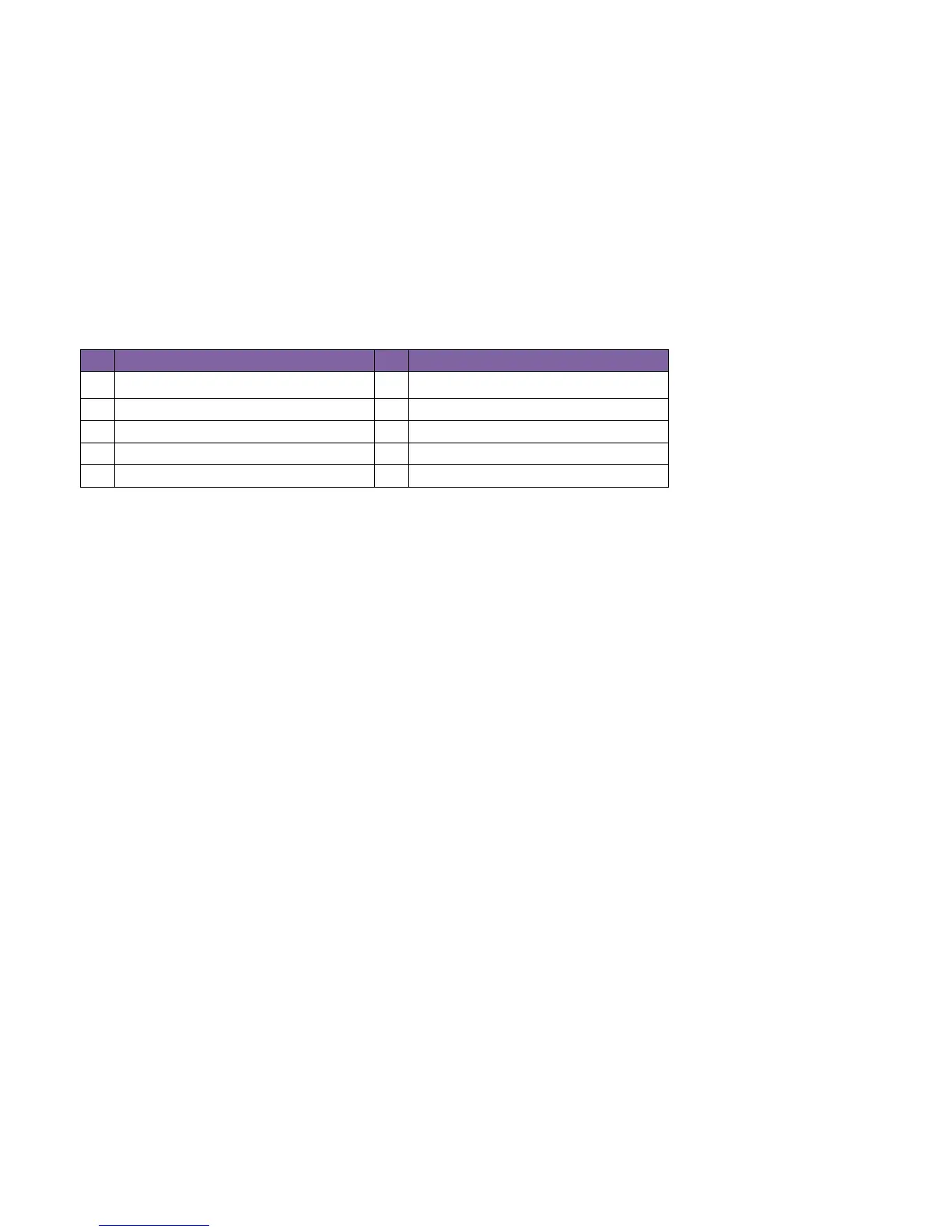
The following table illustrates the pinout of the DE9 serial connector on the HD1022:
pin Description pin Description
1 NC 2 Receive data into the device
3 Transmit data out of the device 4 Available 5V@500mA
5 Ground 6 NC
7 RTS 8 CTS
9 NC -- --
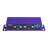
DA15 GPIO
The GPIO switch/led connector is a DA15 female. This connector is used to allow the player to control external LEDs or
other devices requiring 24mA of current or less.
Connect the LED outputs to the LED ANODE and connect the LED CATHODE to the ground. If you want to connect
another device, then the output is capable of sourcing or sinking up to 3.3V at 24mA, but there is a series resistor of 100Ω
in each line.
The connector also allows the connecting of external contact closures to the ground. In order to connect a switch, connect
one side of the switch to the switch input, and connect the other side to one of the ground pins on the DA15 connector.
The connector can also supply 3.3V at up to 500mA to an external device. The 3.3V output is polyfuse-protected and can
source up to 500mA.
If one BrightSign player is driving the inputs on another BrightSign player, then you can drive at most three inputs from
one output. The following calculations explain this limitation: