EasyManua.ls Logo

Brilix XHP 160 User Manual

Default Icon
28 pages
To Next Page IconTo Next Page
Page #1 background imageLoading...
Page #1 background image
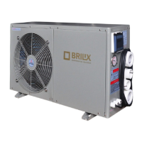
Swimming Pool Heat Pump XHP
INSTALLATION
AND USER GUIDE
Illustrative photo
i
Read the instructions
EN

Questions and Answers:

Brilix XHP 160 Specifications

General IconGeneral
BrandBrilix
ModelXHP 160
CategorySwimming Pool Heater
LanguageEnglish

Summary

1. Specification

1.1 Product Specifications Overview

Details technical specifications for various heat pump models.

2. Performance Curves

Heat Output, Input, and COP Curves

Graphical representation of heat pump performance under different air temperatures.

3. Dimensions

Physical Dimensions of Models

Table showing the physical dimensions (A-H) for each heat pump model.

4. Installation

Installation Illustration and Guidelines

Visual guide and general placement advice for installing the heat pump.

Discharge Connection and Bypass

Diagram and explanation of the water discharge connection and bypass setup.

Installation Position Selection

Recommendations for choosing an optimal and safe location for the heat pump.

Chemical Element Placement

Importance of chemical element positioning for heater longevity and system safety.

5. Electrical Connection

Connection Diagram for XHP 40, 60, 100

Detailed electrical wiring diagram for specific heat pump models.

Connection Diagram for XHP 140

Detailed electrical wiring diagram for the XHP 140 model.

Connection Diagram for XHP 200

Detailed electrical wiring diagram for the XHP 200 model.

6. Initial Heat Pump Start-up and Winterization

Start-up Procedure and Water Flow

Step-by-step guide for initial heat pump operation and water flow switch function.

Time Delay and Winterization

Explanation of time delay features and essential steps for winterizing the heat pump.

Re-starting After Winter

Procedures for safely starting the heat pump after the winter season.

7. Setting Operating Data

Control Display Functions

Overview of control panel buttons and LED display indicators.

Identifying Operating Parameters

Guides on viewing parameters and real-time data on the LED display.

Parameter Settings (0-8)

Detailed settings for parameters 0 through 8, including ranges and factory defaults.

Parameter Settings (9-A) & Mode Identification

Details parameters 9, A, and mode identification parameters B through G.

Parameter H: Electronic Expansion Valve

Details parameter H, which relates to electronic expansion valve intervals.

Adjusting Operational Settings

Covers setting water temperature, locking functions, clock, and timer activation/deactivation.

8. Troubleshooting

Error Codes and Solutions

Lists fault codes, their causes, and recommended solutions for LED display errors.

Faults Without Error Codes

Addresses faults that occur without error codes displayed on the controller.

9. Schematic Representation and Parts List

Component Identification and Diagram

Illustrates components and provides a schematic of the heat pump's internal layout.

10. Spare Parts 1

Major Component Identification

Visual identification of major internal and external heat pump components.

10. Spare Parts 2

Minor Component Identification

Visual identification of smaller components like sensors, valves, and controls.

11. Cabling Diagram

Internal Wiring Diagram Example

Illustrates the electrical connections within the XHP 60 model.

12. Replacement of Parts

Parts Requiring Replacement

Lists common components that may need replacement.

Replacement Procedure and Safety

Provides essential safety warnings and step-by-step instructions for replacing parts.

Warranty Terms and Conditions

Safe Disposal and Claims

Related product manuals