EasyManua.ls Logo

Brilix XHP 200 User Manual

Default Icon
28 pages
To Next Page IconTo Next Page
Page #1 background imageLoading...
Page #1 background image
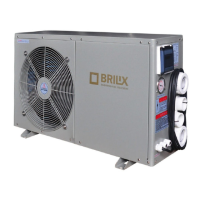
Swimming Pool Heat Pump XHP
INSTALLATION
AND USER GUIDE
Illustrative photo
i
Read the instructions
EN

Questions and Answers:

Brilix XHP 200 Specifications

General IconGeneral
BrandBrilix
ModelXHP 200
CategorySwimming Pool Heater
LanguageEnglish

Summary

1. Specification

1.1 Technical Specifications Overview

Details heat output, power consumption, COP, voltage, current, water data, dimensions, refrigerant, and noise levels for various models.

2. Performance Curves

Heat Output, Input Power, and COP Characteristics

Graphs illustrate heat output, input power, and COP variations with air temperature and water conditions for different models.

3. Dimensions

Unit Dimensions by Model

Table showing physical dimensions (A-H) for different heat pump models, specified in millimeters.

4. Installation

4.1 Installation Layout Diagram

Diagram showing the typical installation layout of the heat pump with surrounding pool equipment like pumps and filters.

4.1.1 Discharge Connection and Bypass

Diagram illustrating the bypass configuration and connection for heat pump discharge to the swimming pool system.

4.2 Installation Position Requirements

Guidelines and diagrams for choosing the optimal location for the heat pump, emphasizing ventilation and accessibility.

4.3 Chemical Element Impact on Longevity

Discusses the impact of chemical elements like chlorine on the heat pump's lifespan and required installation safeguards.

5. Electrical Connection

5.1 Wiring Diagram: XHP 40, 60, 100

Detailed wiring diagram for XHP 40, XHP 60, and XHP 100 models, including essential safety and connection notes.

5.2 Wiring Diagram: XHP 140

Detailed wiring diagram specifically for the XHP 140 model, showing component connections and terminals.

5.3 Wiring Diagram: XHP 200

Detailed wiring diagram for the XHP 200 model, illustrating connections for components like the compressor and fan motor.

6. Operation and Maintenance

6.1 Initial Start-up Procedure

Step-by-step guide for starting the heat pump for the first time, ensuring correct water flow and connections.

Water Flow Switch Functionality

Explanation of the water flow switch's role in protecting the heat pump from damage caused by insufficient water flow.

6.2 Heat Pump Winterization

Instructions and recommendations for preparing the heat pump for winter to prevent damage and maintain warranty.

6.3 Post-Winter Heat Pump Restart

Steps to follow to safely restart the heat pump after the winter season, including system checks and air purging.

7. Setting Operating Data

7.2 Control Panel Functions

Identifies and explains the functions of buttons and indicators on the heat pump's control panel for user interaction.

7.3 Identifying Operating Parameters

Guide on how to navigate and view various operating parameters displayed on the unit's LED screen.

Parameter Settings: Temperature, Defrost, Modes

Details specific parameters (0-8) for setting incoming water temperature, defrost conditions, operating modes, and performance.

Parameter Settings: Performance & Mode Identification

Details parameters (9-G) and explains how to identify the current operating mode and view sensor readings like temperatures.

Parameter H: Expansion Valve Adjustment

Details parameter H for current intervals of the electronic expansion valve and related display notes.

Advanced Setting Functions

Covers setting water temperature, locking functions, clock adjustment, and timer activation/deactivation for the heat pump.

8. Troubleshooting

8.1 Error Codes and Controller Diagnostics

Lists common fault codes, their causes, and recommended solutions for the heat pump controller's LED display.

8.2 Non-Error Code Faults and Solutions

Addresses faults occurring without error codes, detailing causes and solutions for issues like no power or short runs.

9. Schematics and Parts List

Component Layout and Part Identification

Diagram showing component layout and a detailed list of all parts with their corresponding numbers for reference.

10. Spare Parts 1

Major Component Identification

Visual identification of key spare parts like the evaporator, fan motor, valves, and heat exchanger via labeled diagrams.

10. Spare Parts 2

Minor Component Identification

Visual identification of smaller spare parts including sensors, capacitors, valves, and control units.

11. Cabling Diagram

XHP 60 Electrical Wiring

Diagram showing the electrical wiring of the XHP 60 model, detailing connections for the transformer and main controller.

12. Replacement of Parts

Parts for Replacement

Visuals of common parts like filters, expansion valves, pressure valves, suction valves, and manometers for replacement.

Replacement Procedure and Safety Precautions

Detailed instructions and critical safety warnings for replacing heat pump components, including coolant and pressure handling.

Warranty and Service Information

Warranty Terms and Service Claims

Outlines the conditions governing product warranty and the process for lodging service claims with suppliers.

Product Disposal and Servicing Guidelines

Provides guidance on ecologically sound product disposal after service life and general servicing considerations.

Related product manuals