POWER SUPPLY
The power supply is housed in a metal chassis craed from anodized aluminium. This chassis is con-
nected to the ground or “Earth” connecon of the power plug. The power supply should ONLY be
connected to the mains with a three-prong power cord.
The power supply includes a transformer that converts the mains voltage into several discrete volta-
ges as required by various circuits within Nyquist.
One of these voltages is reced and stabilized at 22 VDC. The output is short circuit proof for a
current of 1A and will be shut down by a PTC during short circuit. The other alternang voltages
are used in the preamplier secon. It is important to take care that the connecon cable with the
7-pole connector is not damaged or snapped.
AC POWER CORD
As with all Brinkmann Audio products, Nyquist ships with a purpose-designed, 3-pole mains cord.
Unlike the “Commodity” mains cords supplied with many audio products, this Brinkmann Cord has
been engineered and tuned by Helmut Brinkmann to deliver superior sonic performance with our
products. It is hand built by Brinkmann Audio using rigidly specied cabling and connectors. Alt-
hough many customers will prefer to use aermarket cables, we suggest audioning the supplied
mains cable rst.
DIGITAL MODULE
The digital module of Nyquist is easily re-
movable and exchangeable; consequently,
Nyquist can be upgraded to accommodate
future formats simply by replacing the mo-
dule, rather than replacing the complete
product.
The Nyquist D/A Converter ships with
the digital module installed and ready for
operaon.
Removal and Replacement of Digital
Module:
Always disconnect Nyquist from the mains
before removing the digital module!!
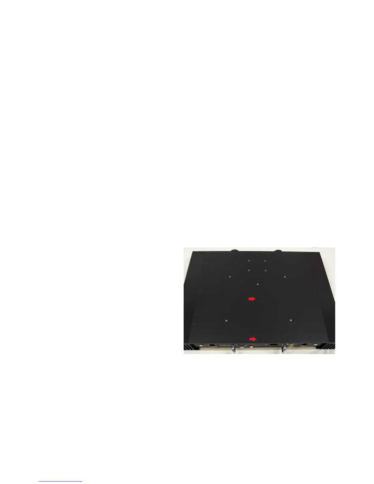
Located on the back panel are two handles to facilitate the secure remove and re-installaon of the
digital module. Nyquist needs to be turned upside down and the two screws (shown in the picture)
removed. Next, return Nyquist to upright posion and slowly, carefully pull out the module with the
handles. For re-installaon please follow the same instrucons in reverse order.
There is no need to remove the digital module unless it needs to be exchanged!
5
 Loading...