1009719 Rev E8.
ASSEMBLY
================================================================================================
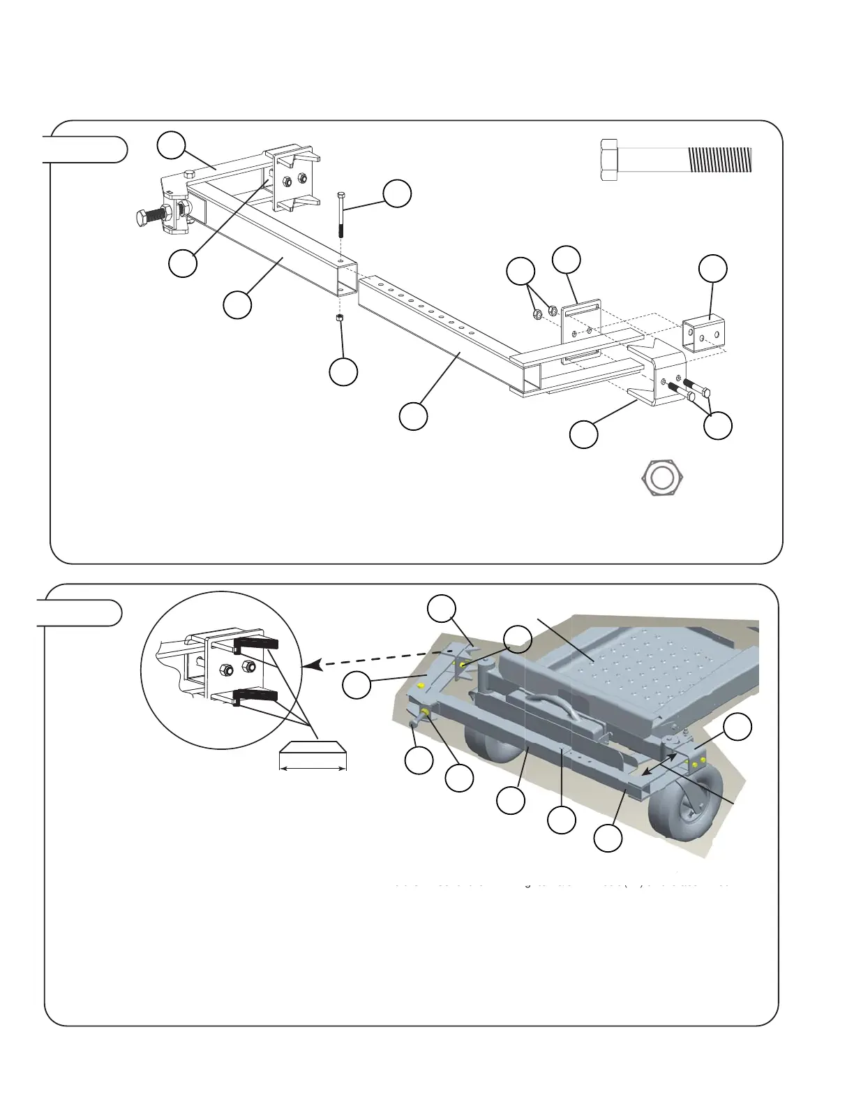
Figure 6.
3/8” Nylon Lock Nut
Qty. 5
4
3/8” x 3-1/2” Hex Bolt
Qty. 5
7
3
4
16
17
4
7
1
7
6
2
8
Slide the clamp plate (3) over the v-bracket (1)
anges then slide the 2” spacer (16) and the 1-3/4”
spacer (8) between them.
Make sure that the v-bracket assembly with the 2”
spacer tube (8) ts with clamp arm (2) and the
v-bracket assembly with the 1-3/4” spacer tube (16)
ts with the xed arm (17).
Insert 3/8” x 3-1/2” hex bolt (7) through all parts
and tighten the 3/8” nylon lock nuts (4) nger tight.
Slide each v-bracket assembly over the ends of the
clamp arm (2) and the xed arm (17)
Tighten the 3/8” nylon lock nuts down completely.
Slide the xed arm (17) into the tube with decal (6)
and bolt the two parts together keeping the 3/8”
nylon lock nut nger tight for adjustment later.
Figure 7.
NOTE: Before installing support frame on
ZTR be sure to apply the rubber edging
(42) to each v-bracket. Verify and cut 8
pc approximately 3.0” long. There is 30.0”
of rubber edging (42) provided with the
dethatcher
ZTR Mower
TWO PEOPLE ARE RECOMMENDED FOR ATTACHING THE MOUNT TO THE ZTR
Pivot clamp arm (2) out as shown to allow it to be easily attached. With a partner hold the mount up to the casters of the tractor and swing the
clamp arm back in so that it interfaces with the cylindrical tube above the wheel of the ZTR. Tighten 3/8” x 4” bolt (12) till the acorn nut
interfaces that dimple plate located on the tube with decal (6). With a 15/16” wrench tighten 3/8” x 4” bolt (12) until mount is firmly attached to
the ZTR, the ideal position of the clamp arm (2) when fully tightened it perpendicular (90°) to the tube with decal (6).
Note:
1) If clamp arm (2) is not perpendicular to tube with decal (6) loosen the 3/8” x 4” bolt (12) and remove mount. Remove 3/8” x 3” bolt (3) and
3/8” nut (4) and move tube with decal in or out over fixed arm mount (17) to readjust depending if you need to fit a smaller or wider frame
respectively.
2) To keep the gap between the back of the mount and the front of the ZTR as small as possible the two “V” brackets (1) can be adjusted by
losening the 3/8” lock nut (12) and sliding the entire assembly back toward the front of the ZTR. Always keep the mount parallel with the front of
the ZTR.
Once adjustments are made ensure that all nuts and bolts are tightened and that the mount is VERY secure to the front of the ZTR.
Approx.
3.0” verify
measurement
cut ends at 45
degrees
ZTR M
w
r
NT T
THE ZT
With a
rtner hold the mount u
to the casters o
the tra
tor and swi
t
ove the wheel of the ZTR. Tighten 3/8” x 4” bolt (12) till the acorn nut
7
2
6
12
17
11
4
1
1
See
note 2
 Loading...