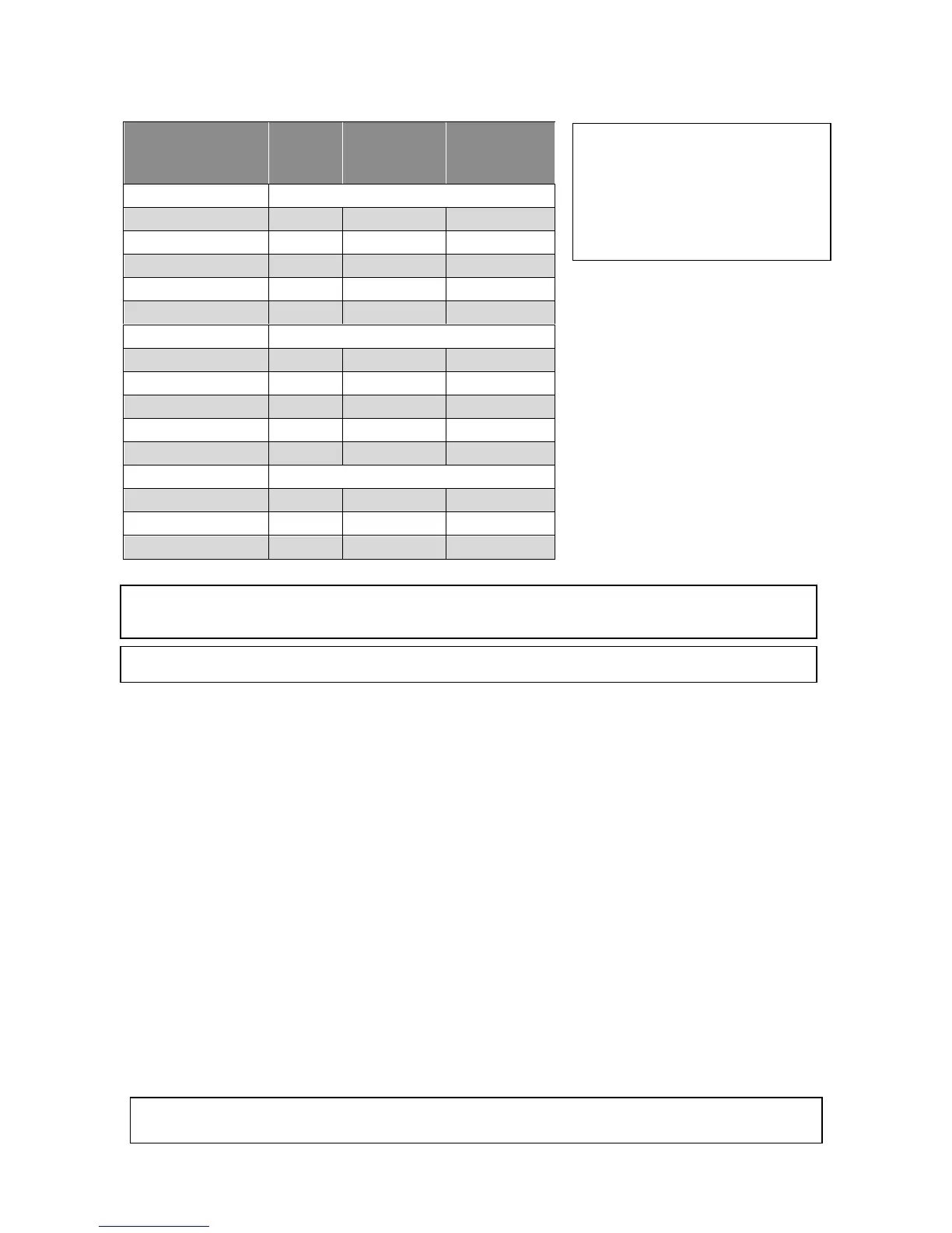
The outlet chart has been divided into two columns as follows:
Table 5: Outlet chart
Model
Airflow
Rate
(l/s)
A
Maximum
Outlets
B
Minimum
Outlets
BX3 Models
BX315 (300mm)**
498 8 4
BX320 (300mm)**
581 11 5
BX320 (350mm)**
622 11 5
BX326 (350mm)**
819 16 8
BX326 (400mm)**
921 16 8
2PWN Models
2PWN15
452 10 5
2PWN20
527 13 7
2PWN20 XA
561 13 7
2PWN26
858 17 8
2PWN26 XA
944 17 8
DF3 & UF3 Models
DF320 XA
625 11 5
UF320 XA
550 11 5
UF326 XA
800 17 8
**Model and (Base Box Pop) size
9.0 Thermostat Installation
All Brivis heating systems can be controlled by various Brivis Thermostats, each explained in detail below. A
Thermostat inside the house is wired to the control module in the heater. The Thermostat monitors the
temperature in the house and switches the system ON and OFF in order to maintain a set temperature. So it
must be positioned correctly.
• Install in the living area: It is important that the Thermostat is placed in a position that will provide the
most accurate reading of the temperature, i.e. in the area most often used for family living.
• Attach on an internal wall: The temperature difference on an external wall can also affect it, so always
mount it on an internal wall. Keep hole in the wall for the wiring as small as possible to prevent draught
from within the wall cavity affecting the temperature setting.
• Get the height right: The Thermostat should be approximately 1500mm above the floor level.
• Avoid hot spots: Keep it as far away as possible from warm air outlets, radiation from the sun,
fireplaces, radio and television sets, or warm pipes and duct running in the wall behind it.
• Avoid cold spots: Keep it as far away as possible from draughts caused by doorways, stairwells,
windows or return air inlets.
• Avoid dead spots: Keep it away from areas of less than normal air circulation, e.g. behind doors, in
alcoves or corners.
• Interference from other electrical connections: Ensure the Thermostat and wiring is kept away from
other electrical, data and antenna cables. This includes keeping the Thermostat’s wiring away from the
spark igniter loom within the heater’s cabinet.
• Use the right cables: Ensure the cable is 0.75mm² in cross section and less than 100m in length.
Note: Airflow figures are based on a total static pressure of 125Pa for the 26 kW model, and 50Pa for
the 15kW and 20kW models.
Note: The maximum and minimum number of outlets detailed in Table 5 are as per AGA specification.
Do not install the control wiring with the power turned on, as the fuse may blow, which would not
be covered under warranty.
A. The maximum number of outlets
that should remain fully open for a
ceiling outlet system.
B. The minimum number of outlets
that should remain fully open for
floor/ceiling systems.
 Loading...