This document describes the Marti SR-30 and SR-40A RPU Receivers, which are integral components of a high-quality FM, synthesized, point-to-point, line-of-sight radio communications link designed for remote broadcast applications. The SR-30 is a dual-channel unit programmable on any two frequencies within a 50 MHz band, while the SR-40A offers frequency agility within a 50 MHz band. These receivers, when paired with Marti SRPT-30 and SRPT-40A Transmitters, enable complex systems with multiple relay (repeaters), bi-directional (full duplex), and automatic switching standby features. Both models are available in a wide range of band models, detailed in the "SPECIFICATIONS & ORDERING" section.
Important Technical Specifications:
- Frequency Bands: Refer to the ordering information for specific bands.
- Technology: Phase-locked loop; synthesized.
- Frequency Agility and Accuracy: Programmable in 100 Hz increments with an accuracy of ± 1%.
- Operating Temperature Range: -10°C to +50°C.
- Frequency Stability (over operating temperature range): 0.0001%.
- Signal-to-Noise @ 100 uV Input:
- 36 kHz BW @ 5.4 kHz Dev: Greater than 57 dB.
- 25 kHz BW @ 3.6 kHz Dev: Greater than 53 dB.
- 10 kHz BW @ 1.2 kHz Dev: Greater than 44 dB.
- Frequency Response: ± 1.5 dB of the specified bandwidth.
- Distortion: 2% or less of the specified bandwidth.
- Spurious Response: -90 dB.
- RF Input Impedance: 50 ohms.
- RF Connector: Type N-Female.
- Output Level: -10 to +11 dBm.
- Output Impedance: Balanced, 600 Ohms, 15-pin D-Type connector.
- Sensitivity:
- 0.5 microvolts for 20 dB signal-to-noise.
- 2 microvolts for 30 dB signal-to-noise.
- 4 microvolts for 40 dB signal-to-noise.
- 100 microvolts for maximum signal-to-noise, typically 57 dB or greater.
- Power Requirements: 85 to 264 VAC, 47 to 63 Hz, or external DC operation on +10 to +14 VDC.
- Approximate AC Current Requirements: 1.5 Amps.
- Accessory Connector: 15-pin D connector.
- Weight: Net 6.7 pounds (3.0 kilograms).
- Dimensions: 3.5 in. high x 12 in. wide x 15 in. deep (8.9 cm. high x 30.5 cm. wide x 38.1 cm. deep).
- Regulatory: FCC, DOC.
Usage Features:
The SR-30/SR-40A receivers are designed for both portable and rack-mounted use. They feature a switching power supply that operates on any AC voltage from 85V to 264V (47 to 63 Hz) and can also be powered by an external +10 to +14 VDC source.
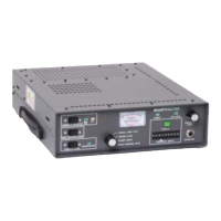
Front panel controls and indicators provide comprehensive monitoring and adjustment capabilities:
- Metering/Indicators: An illuminated meter displays signal level, decode level, power supply level, and mono program output level. LEDs indicate MAX Signal, ATT Signal, UNSQUELCHED, POWER, AFC LOCK, and F1/F2 (on SR-30 models).
- SIGNAL ATTENUATION Control: Adjusts a variable attenuator at the converter input to minimize unwanted signals from intermodulation. The MAX SIG indicator illuminates when the attenuator is off, and the ATT indicator illuminates when attenuation is applied. The level of attenuation can be viewed on the multimeter.
- MONO PROGRAM LEVEL Control: Adjusts the audio output level from -10 dBm to +11 dBm, with the level displayed on the multimeter. This control offers both rapid and fine (0.150 dB increments) adjustments.
- SQUELCH LEVEL Control: Controls the level at which the receiver will squelch. The UNSQUELCHED indicator illuminates when the receiver is unsquelched.
- HEADPHONE Receptacle/Level Control: A 1/4-inch stereo headphone receptacle is provided for monitoring audio, with a dedicated level control. A 40 Ohm or greater headphone impedance is required.
- Frequency Selection:
- SR-30 Models: Feature an F1/F2 switch to toggle between two pre-programmed frequencies. The AFC LOCK indicator flashes quickly to indicate a frequency change.
- SR-40A Models: Utilize nine FREQUENCY SELECT pushwheel switches to enter a 9-digit operating frequency, which is then assigned by depressing the EXECUTE switch. The AFC LOCK indicator flashes quickly upon frequency change.
- Automatic Frequency Control (AFC): The AFC LOCK indicator illuminates when the receiver is locked to the selected frequency and flashes if it becomes unlocked.
- Microcontroller: A programmed microcontroller manages front-panel switch and indicator control, AFC lock control, and metering control.
- Auto Recovery: The unit automatically recovers from loss of AC/DC power.
- Subaudible Tone Decoder: Available for signaling, automation control, or automatic repeater functions.
- Squelch Relay: Contacts are available for external switching.
Maintenance Features:
The manual emphasizes the importance of proper installation and provides guidelines for maintaining optimal performance and safety.
- Unpacking & Inspecting: Detailed instructions for inspecting shipments for damage or shortages, and retaining packing materials for potential returns.
- Installation:
- Requires installation in a well-ventilated, well-grounded, and shielded rack cabinet.
- Avoid locating near equipment with strong magnetic fields or high temperatures.
- All equipment racks and cabinets should be bonded together by wide copper grounding strap for RF ground potential.
- Proper connection of the receiving antenna coax to the N-type connector on the rear panel is crucial.
- Balanced program audio output is available via a 15-pin D-Type accessory connector.
- Strict adherence to power requirements, including using a 3-prong grounded outlet for AC and observing DC voltage limits (+14V max).
- Rear-panel ground terminal for earth grounding.
- Mobile Repeater Connections: Specific instructions for mobile installations, including cabling, grounding to the vehicle body, and antenna installation.
- Antenna Safety: Emphasizes extreme caution during antenna installation to avoid contact with power lines and to minimize exposure to RF radiation. Recommendations include locating antennas away from people and equipment susceptible to RF radiation and referring to ANSI C95.1.
- Antenna Installation Checklist: Suggestions to avoid costly errors, including careful assembly, proper transmission line connector assembly (avoiding RG-58U or RG-8U for RPU antennas due to loss), moisture proofing, and correct coaxial cable location and grounding.
- Tune-Up and Adjustments:
- WARNING: Adjustments should only be performed by highly trained technicians using laboratory-grade test equipment. AC line voltage is present on power supply terminal strips during adjustments.
- IF Amplifier/Detector Circuit Board Adjustments: Involves connecting an RF signal generator, voltmeter, and distortion analyzer to adjust coils and potentiometers for desired voltage indications, minimum distortion, and maximum output level.
- Decode Board Circuit Board Adjustments: Requires an encoded Marti transmitter as a signal source to adjust sensitivity and decode frequency controls, and the relay control.
- Power Supply/Meter Calibration: Involves connecting a voltmeter to a test point on the front panel circuit board to adjust SVR1 on the power supply and R65 on the front panel circuit board for a 12V DC indication on the multimeter.
- Bill of Material: Detailed lists of parts for both SR-30 and SR-40A models, including descriptions, quantities, and reference designators, organized in an indented structure to show sub-assembly relationships.
- Schematics: Provides detailed schematic diagrams for various circuit boards and components, including the I/O Filter, IF Filter, IF Amplifier/Detector, Audio Board, and Front Panel.