4
©2011 Broadcast Electronics
Unpack equipment immediately up-on receipt and thoroughly inspect for concealed damage. If damage is
discovered, stop further unpacking and request immediate inspection by local agent of carrier. A written
report of the agent's findings, with his signature is necessary to support claim. Check your shipment against
the shipping papers for possible shortage. Do not discard any packing material until all items are accounted
for. Small items are often thrown away with packing material.
Packing material should be retained until equipment testing is completed. Any equipment returned to the
factory should be packed in original cartons, insured, and pre-paid.
2 Installation
IMPORTANT NOTICE
This equipment must be operated in a well-ventilated rack cabinet.
Install rack-mounted equipment in a well-ventilated, well-grounded, and shielded rack cabinet. Do not
locate solid-state equipment in a rack above tube-type equipment, which produces high temperatures.
Problems can also be avoided by locating this unit away from other equipment, which has transformers
that produce strong magnetic fields. These fields can induce hum and noise into the Marti equipment thus
reducing performance. Strong radio frequency (RF) fields should be avoided where possible. Extensive
shielding and filtering has been incorporated into this equipment to permit operation in moderate RF
environments. All equipment racks, cabinets, etc. should be bonded together by wide copper grounding
strap to ensure that all system elements are at RF ground potential.
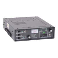
2.1 STANDARD CONNECTIONS
1. Connect the receiving antenna coax to the ANTENNA TYPE N port on the rear–panel using a
type–N male connector. A short flexible jumper, 20 inches maximum, may be used between the
ANTENNA port and the Heliax. Marti Part No. 585–017 Double–Shielded, Low–Loss RG–214/U
jumper is recommended.
2. Balanced program audio output is located at accessory connector J4–4 and J4–5 (refer to Figure 1).
The output level can be adjusted from –10 to +11 dBm. Refer to the accessory kit and locate the
15–Pin D–Type mating connector. Connect shielded audio cable to J4–4 and J4–5. If unbalanced
audio is desired, connect the cable between J4–4 (signal) and J4–1 (ground). Once the audio cable
is installed, connect the mating connector to the J4 receptacle on the rear–panel.
CAUTION
IF DC OPERATION IS REQUIRED, DO NOT APPLY MORE THAN +14V
TO THE UNIT.