11
4 OPERATION
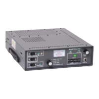
4.1 CONTROLS AND INDICATORS
4.1.1 SIGNAL ATTENUATION CONTROL
The SIGNAL ATTENUATION control adjusts a variable attenuator at the input of the converter. This control is
designed to minimize the reception of unwanted signals during interference conditions. These conditions are
due to extremely high intermodulation from a combination of neighboring signal frequencies. This unwanted
signal can be reduced or eliminated by attenuating the received signal using the SIGNAL ATTENUATION
control. However, the desired signal will also be attenuated and may result in degraded audio performance.
The SIGNAL ATTENUATION MAX SIG and ATT indicators present the state of the attenuator. When the MAX
SIG indicator is illuminated, the attenuator is off (maximum input signal level). When the ATT indicator is
illuminated, the attenuator is reducing (attenuating) the input signal level. The level of signal attenuation is
indicated by operating the front panel multimeter switch to SIGNAL LEVEL (ATT).
To raise the attenuation level, depress the SIGNAL ATTENUATION , section of the control. The ATT
indicator will illuminate and the input signal level will be lowered as viewed on the multimeter. To lower the
attenuation level, depress the SIGNAL ATTENUATION ' section of the control. The input signal level will
raise as viewed on the multimeter.
Typically, the control is adjusted to provide maximum signal to the receiver. As a result, the MAX SIG
indicator will illuminate. Adjust the control only to reduce unwanted signals during extreme interference
conditions.
4.1.2 MONO PROGRAM LEVEL CONTROL
The audio output level is adjusted using the MONO PROGRAM LEVEL control. The audio level can be adjusted
from –10 dBm to +11 dBm. Observe the audio level by operating the multimeter switch to MONO
PROGRAM LEVEL.
To adjust the output level, operate the multimeter switch to MONO PROGRAM LEVEL. To raise the output
level, depress the MONO PROGRAM LEVEL , section of the control. To lower the output level, depress the
MONO PROGRAM LEVEL ' section of the control. Adjust the audio level until the desired output level is
displayed on the multimeter.
The control can be operated using two methods. If the control is depressed and held, the level will change
rapidly. If the control is momentarily depressed, the level will change in approximately 0.150 dB increments.
4.1.3 SQUELCH LEVEL CONTROL
The level at which the receiver will squelch is controlled by the SQUELCH LEVEL control. The UNSQUELCHED
indicator illuminates to indicate the receiver is unsquelched. The squelch level is raised by depressing the
SQUELCH LEVEL , A section of the control. The squelch level is lowered by depressing the SQUELCH LEVEL 'f
section of the control. To adjust the control, proceed as follows: