INSTALLATION MANUAL
INSTALLATION
13
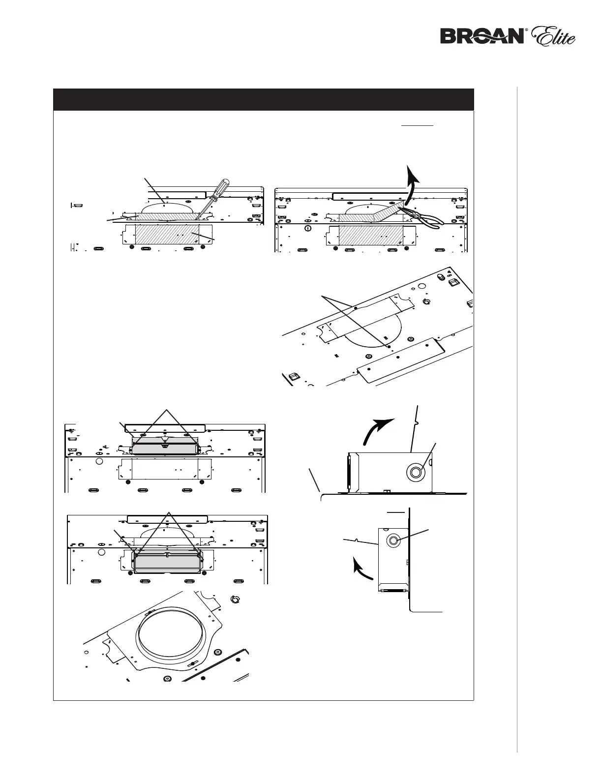
3¼” x 10” OR 7” ROUND DUCTED INSTALLATION ONLY
TIP: Insert a small length of duct over the 3¼” x 10” damper assembly (for rectangular ducting) or
7” round (for round ducting) and seal the joint using aluminum foil duct tape to ease connection
with the house ductwork.
12 ] Remove 3¼” x 10” vertical, 3¼” x 10” horizontal (both are the rectangular central
knockout plates, see hatched areas) or 7-inch round knockout plate as appropriate for
your ducting method (see FIGURES 1 A and 1 B).
NOTE: To accommodate off-center
ductwork, the 7” round duct plate
can be installed up to 1/2” on
either side of the hood center.
7” ROUND KNOCKOUT
PLATE (ALSO REMOVE
3¼” X 10” VERTICAL
KNOCKOUT PLATE)
3¼” X 10”
VERTICAL
KNOCKOUT
PLATE
3¼” X 10”
HORIZONTAL
KNOCKOUT
PLATE
FIGURE 1 A
13 ] Using the screws located on top of the
hood (FIGURE 2), attach the 3¼” x 10”
Damper Assembly on top OR back of hood
(if using 3¼” x 10” duct; shaded part in
FIGURE 3 A below) or 7” Round Duct Plate
(if using 7-inch round duct, FIGURE 4) over
the knockout opening. When installed, the
3¼”x 10” damper assembly must open as
shown in FIGURE 3 B.
FIGURE 1 B
3¼” X 10”
DAMPER
ASSEMBLY
TOP/BACK
EDGE OF
HOOD
DAMPER
FLAP
PIVOT
SCREWS
FIGURE 3 A FIGURE 3 B
3¼” X 10”
DAMPER
ASSEMBLY
BACK OF
HOOD
DAMPER
FLAP
PIVOT
SCREWS
SCREWS
FIGURE 2
FIGURE 4