Do you have a question about the Brocade Communications Systems ICX 6610 and is the answer not in the manual?
Explains the meaning and severity of different types of notices (NOTE, ATTENTION, CAUTION, DANGER).
Defines formatting conventions like bold, italic, and courier font for text elements.
Provides contact methods (online, phone, email) for Brocade customers.
Advises OEM customers to contact their OEM/solution provider for support.
Refers to the appropriate configuration guide for supported hardware features.
Summarizes enhancements in FastIron release 08.0.30, focusing on technical specifications.
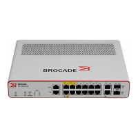
Describes the different hardware platforms and models of the ICX 6610 switch.
Explains the format for specifying data port addresses (stack unit/slot/port).
Explains the format for specifying stacking port addresses (stack unit/slot/port).
Explains how to specify the management port address.
Instructions for verifying the contents of the shipping carton.
Lists the items included in the shipping carton for the ICX 6610 device.
Outlines the need for a management station and serial connection for initial setup.
Provides general safety precautions, including a warning about laser radiation.
Provides specifications for cables used with different port types and lengths.
Step-by-step instructions for installing the ICX 6610 on a desktop or flat surface.
Details the dedicated stacking ports and how they can be grouped into trunks.
Summarizes stacking ports on ICX 6610 and ICX 6450 for mixed stack configurations.
Describes a single ring configuration with two ICX 6610 backbone and ICX 6450 peripheral devices.
Covers hot-swapping precautions and procedures for installing/replacing power supplies.
Explains the importance of assigning passwords to secure CLI access.
Provides steps for setting Super User, Port Configuration, and Read-Only passwords.
Details the procedure to recover a lost password via serial access and system reset.
Details configuring IP addresses on Ethernet ports, VE interfaces, and loopback interfaces.
Refers to the Hardware Specifications chapter for port pinout details.
Refers to the Cabling Infrastructure section for cable lengths and types.
Explains using crossover or straight-through cables for Ethernet connections.
Explains how to ping an IP address to verify network reachability.
Describes how to interpret LEDs to determine network connection status.
Explains how to display and change temperature warning and shutdown levels.
Lists enclosure, power, cooling, and system architecture specifications.
Details GbE ports, SFP GbE ports, and Ethernet management port types.
Specifies the types and status indications for Port, System, Power, and Fan LEDs.
Lists the serial cable type for management.
Explains how to diagnose issues by observing switch LEDs.
Explains how to access the switch management agent via Telnet or SSH.
Provides Class A warning for radio interference in domestic environments.
States compliance with Canadian Interference-Causing Equipment Regulations.
Alerts to hazards like high ambient temperature and restricted airflow.
States that procedures are for qualified service personnel only.
Warns about hazards before installation and during power cord removal.
| Brand | Brocade Communications Systems |
|---|---|
| Model | ICX 6610 |
| Category | Switch |
| Language | English |