Brookfield Engineering Laboratories, Inc. Page 13 Manual No. M/85-150-N898
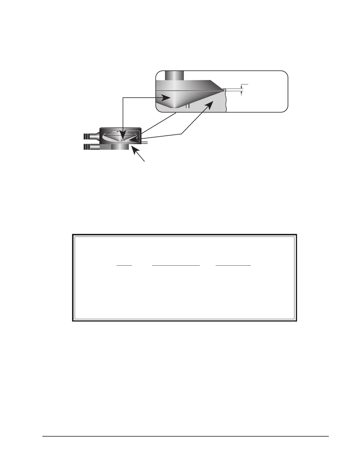
Each of the five available cones has a specific sample volume, as shown in Table A1. Note that the correct
amount of sample fluid should cover the cone face and back up over the edge less than 1mm as shown
in (Figure A8).
Figure A8
Notes: a) The cup may be removed without resetting the gap.
b) Remove the spindle from the viscometer when you clean it.
c) Refind the hit point every time the spindle is attached.
Table A1
Cone Sample Volume Cone Angle
CP-40 0.5 ml 0.8°
CP-41 2.0 ml 3.0°
CP-42 1.0 ml 1.565°
CP-51 0.5 ml 1.565°
CP-52 0.5 ml 3.0°
Sample
Cup
Cone
Less than
1 mm
Cone
Less Than
1 mm
Cup
Sample
Calibration Procedure using Cone/Plate Viscometer
1) Ensure that the circulating bath used maintains the stated calibration temperature to within
± 0.1°C.
2) The attachment of the cone spindle and sample cup, and the gap setting between the cone and
cup must be accomplished by following "Cone/Plate Rheometer Set Up" Procedure.
3) Put the proper amount of viscosity standard fluid into the sample cup. The amount varies per
cone spindle (refer to Table A1).