Do you have a question about the Brookfield CAP 2000+L and is the answer not in the manual?
Lists all included and optional items for the viscometer.
Details electrical requirements, fuses, and power cord color codes.
Outlines torque range, speeds, temperatures, weight, and materials.
Provides detailed physical dimensions of the viscometer in inches.
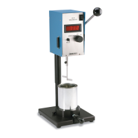
Step-by-step guide for physically setting up the viscometer.
Explains safety symbols and provides general safety guidelines for operation.
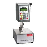
Describes the function of each key on the viscometer's control panel.
Explains how viscosity and temperature are displayed on the unit.
Provides instructions for cleaning the instrument, components, and solvent trap.
Details how to turn on the viscometer and initial start-up screens.
Guides on choosing, attaching, and setting the cone spindle.
Instructions for setting the rotational speed of the spindle.
How to set and manage the sample temperature for testing.
Sets the delay time before spindle rotation begins for equilibrium.
Sets the duration for spindle rotation during a measurement.
Explains how to print test results and headings.
Describes the functions of the RUN and STOP/ESCAPE keys.
Shows the display of key measurement parameters during operation.
Explains Full Scale Range (FSR) and how it relates to torque models.
Details the accuracy specifications for viscosity and temperature measurements.
Procedures for verifying the viscometer's calibration accuracy.
Instructions for performing cone calibration using standard fluids.
Discusses the repeatability of the CAP 2000+ Viscometer.
Recommended procedure for performing viscosity measurements.
How to operate the viscometer using PC control software.
| Brand | Brookfield |
|---|---|
| Model | CAP 2000+L |
| Category | Measuring Instruments |
| Language | English |