Do you have a question about the BROSA 0201 and is the answer not in the manual?
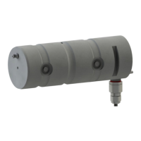
The BROSA Type 0201 & 0203 Force Measuring Pin is a device designed for measuring force in double shear connections in or on machines and devices of all kinds. It is a cylindrical measuring body that absorbs the load and exhibits properties for torsional and axial securing. The device is equipped with a connection support (2) firmly connected to the measuring body, which in some cases, or if not placed directly on the measuring body, contains the necessary elements for the electrical connection (plug or cable, 3). The measuring body also contains the measurement electronics (1b). The recess (1b) in the measuring body for technical measurement reasons can be provided with a filling depending on the application, optionally on request. Optionally, the measuring body can contain elements to lubricate the bearing (1c). The Ex d Type 0203 force measuring pin is always equipped with a threaded pin (4) for electrical potential equalisation (optional in the other types). The measuring body and connection support are made of stainless steel. The MOP force measuring pin incorporates integrated mechanical overload protection.
The force measuring pin (1) is inserted into the mounting holes (2) of the double-shear connection and secured against unintended movement by means of a pin holder (see Fig. 1, point 1a). Force is transmitted from the connection to the measuring electronics through analysis of the resulting deformation of the measuring body and output as an electric signal. Versions with two measuring directions (X-Y force measuring pin) and/or two measuring systems, either with output signals on separate connectors/cables or combined in one plug/cable, are available as options.
The device is equipped with a nameplate containing the respective information applicable for the given product. Depending on the structural design, it can be attached either on the front (Figure 3, 1a) or on the long sides (Figure 3, 1b). The measuring direction is indicated on the front side with an arrow (Figure 3, 2). A simplified indication of the measuring direction (omission of the two lower arrows shown in Figure 3) is possible. In the optionally available version with two measuring directions, the measuring directions are labelled as shown in Figure 4.
BROSA force measuring pins are delivered in transport-safe packaging. It is recommended to remove the sensors from the package immediately prior to installation. The mass of the force measuring pin must be observed when selecting appropriate handling equipment and/or lifting gear; it is indicated on the nameplate. BROSA force measuring pins must be secured against falling. Do not throw sensors! Using the pin as a tool (e.g., impact, slotting or lever tool) is not permitted, as it can cause damage to the sensor and thus falsify the measurement results.
BROSA force measuring pins operate automatically; attaching tools is not required for operation. Direct manual intervention by the operator is not necessary; there are therefore no requirements for the operator to wear protective equipment during operation. However, the relevant requirements for the device in which the force measuring pin is implemented must be observed. BROSA force measuring pins emit neither airborne acoustic noise nor non-ionizing radiation. Operation of BROSA force measuring pins is permitted only within the parameters and properties given in the technical datasheets and on the nameplate. These are, among others:
It must be ensured that no parasitic influences such as forces transverse to the measuring direction are transmitted via the force measuring pin. Inductive or capacitive coupling with the connection cable(s) of the sensor can distort the measurement result and must be avoided. Some examples of these kinds of couplings can be caused e.g., by unfavourable cable routing (parallel power lines, frequency converters, transformers, motors, incorrect grounding/shielding and the like). When performing electric welding in the vicinity of the sensor, all connections must be disconnected and isolated. It must be ensured that no welding current is flowing through the sensor. Operation outside the specified parameters or contrary to existing properties or improper use can damage the sensor and cause it to fail or lead to faulty measuring results. If the sensor is overloaded, this can lead to the whole machine being equally overloaded and possibly endangering its stability.
In its capacity as a sensor, BROSA force measuring pins are maintenance-free. As load-transmitting elements, however, they are subject to mechanical stress, requiring regular inspections of the fault-free state of each force measuring pin. The intervals between inspections depend on the intensity of use and must be determined by the end-user. Additional lubrication holes are not necessary for the sensor to function, but are used to lubricate secondary components, so the end-user is responsible for the lubrication cycles. An inspection includes the following points:
The causes of existing errors are to be identified and remedied. If the test indicates an improper sensor state, it must be taken out of operation. If a malfunction or damage is detected on the sensor, it must be sent to the manufacturer's factory for diagnosis and, if necessary, repaired. The sensor may only be repaired at the factory. Intervention (e.g., opening, mechanical processing and the like) done by parties other than the manufacturer means the safe operation of the sensor is no longer ensured and voids the guarantee and warranty.
We recommend performing the following actions in the order given:
If the force measuring pin is to be reused, it must not be removed using impact tools!
If the end of the service life is reached, the force measuring pin is to be disposed of in an environmentally friendly way. Since the non-metallic components are a small proportion compared to the mass of the force measuring pin, it can be recycled as a whole as scrap steel. BROSA sensors are usually made of stainless steel and can be disposed of accordingly. If the sensor is stored before final disposal, an appropriate storage location is to be selected which prevents harmful substances from entering the environment. If necessary, the sensor must be cleaned. BROSA force measuring pins contain traces of environmentally hazardous substances. This is also true of the impurities created during use. Contamination of the environment by these substances is to be prevented.
| Brand | BROSA |
|---|---|
| Model | 0201 |
| Category | Measuring Instruments |
| Language | English |