BROSA Force Measuring Pin
© 2021 BROSA AG, Tettnang, Germany English translation of the original
German document
6 / 15
...............................................................................................................................................................
................................
................................
................................
................................
...............................
............................................................................................................................................................
................................
................................
................................
................................
............................
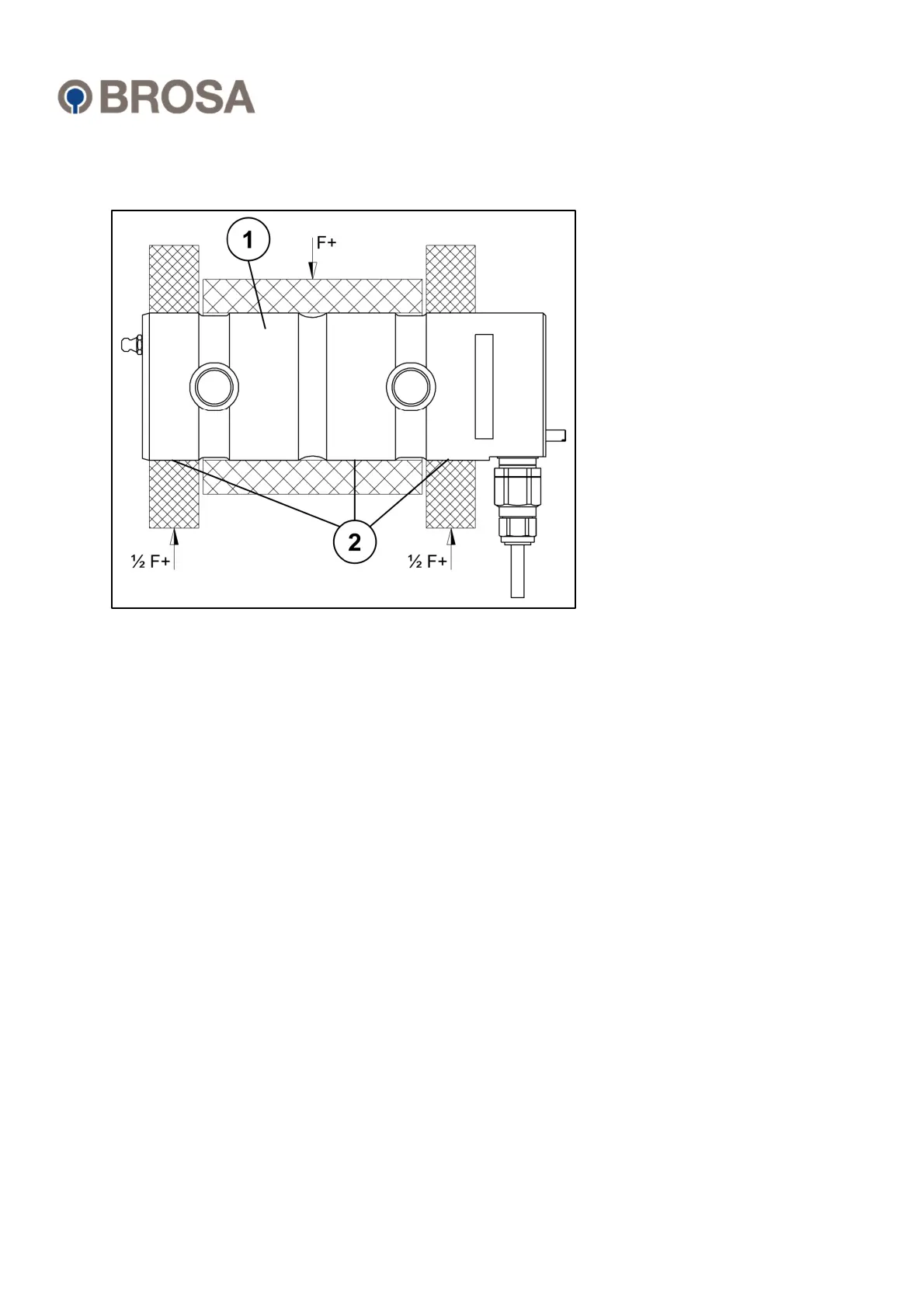
Figure 2: Installation conditions
The force measuring pin (1) is inserted into the mounting holes (2) of the double-shear
connection, which have a corresponding diameter, and secured against unintended
movement by means of a pin holder (see Fig. 1, point 1a). Force F transmitted from the
connection is transmitted to the measuring electronics through analysis of the resulting
deformation of the measuring body and output as an electric signal.
Versions with two measuring directions (X-Y force measuring pin) and/or two measuring
systems, either with output signals on separate connectors/cables or combined in one
plug/cable, are available as options. More information can be found in the technical
datasheets, which can be obtained free of charge from BROSA.