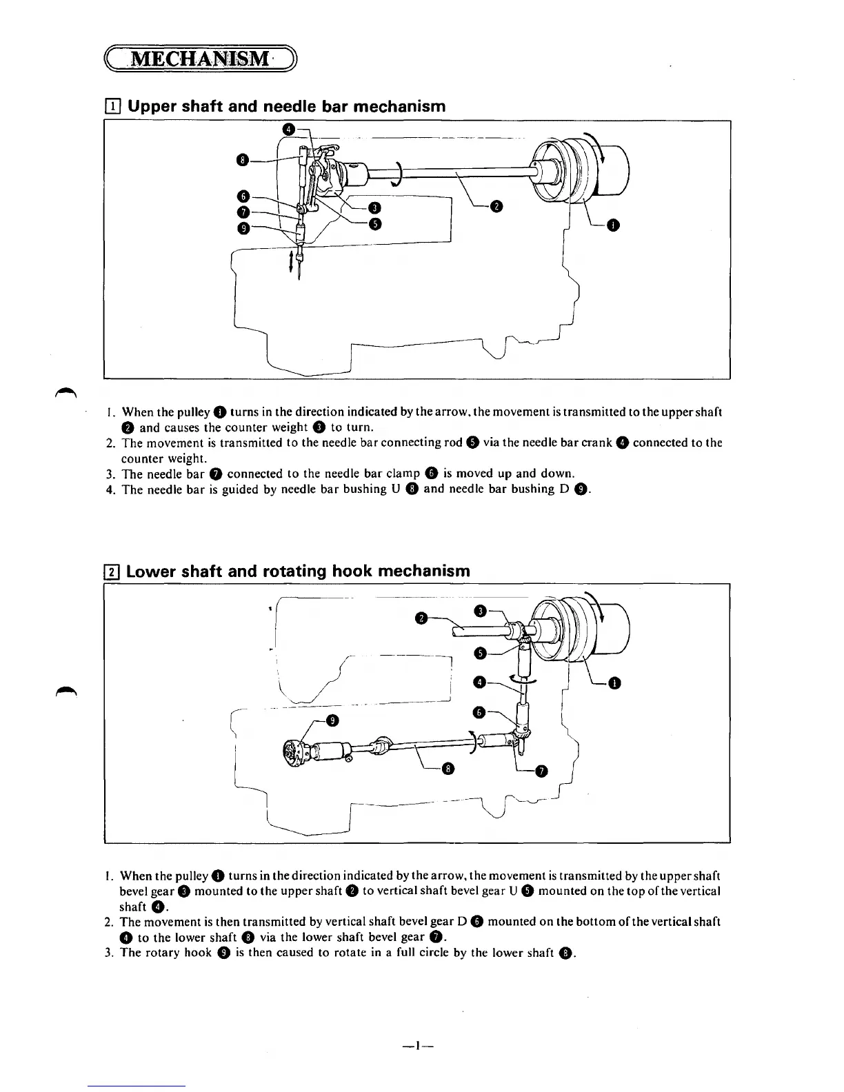
[I] Upper shaft and needle bar mechanism
I. When the pulley 0
turns
in the direction indicated by
the
arrow,
the
movement
is
transmitted
to
the
upper
shaft
8
and
causes the
counter
weight 8
to
turn.
2.
The
movement
is
transmitted
to
the needle
bar
connecting rod 8 via the needle
bar
crank
8 connected
to
the
counter
weight.
3.
The
needle
bar
8 connected
to
the needle
bar
clamp
8
is
moved
up
and
down.
4.
The
needle
bar
is
guided by needle
bar
bushing U 0
and
needle
bar
bushing D
0.
[I] Lower shaft and rotating hook mechanism
I. When the pulley 0
turns
in the direction indicated by
the
arrow, the movement
is
transmitted by the
upper
shaft
bevel
gear
8
mounted
to
the
upper
shaft 8
to
vertical
shaft
bevel
gear
U 8
mounted
on
the
top
of
the vertical
shaft
G.
2.
The
movement
is
then
transmitted by vertical shaft bevel
gear
D 8 mounted
on
the
bottom
of
the vertical shaft
8
to
the
lower
shaft
0 via the lower shaft bevel
gear
8.
3.
The
rotary
hook 0
is
then caused
to
rotate in a full circle by the lower shaft
0.
-I-