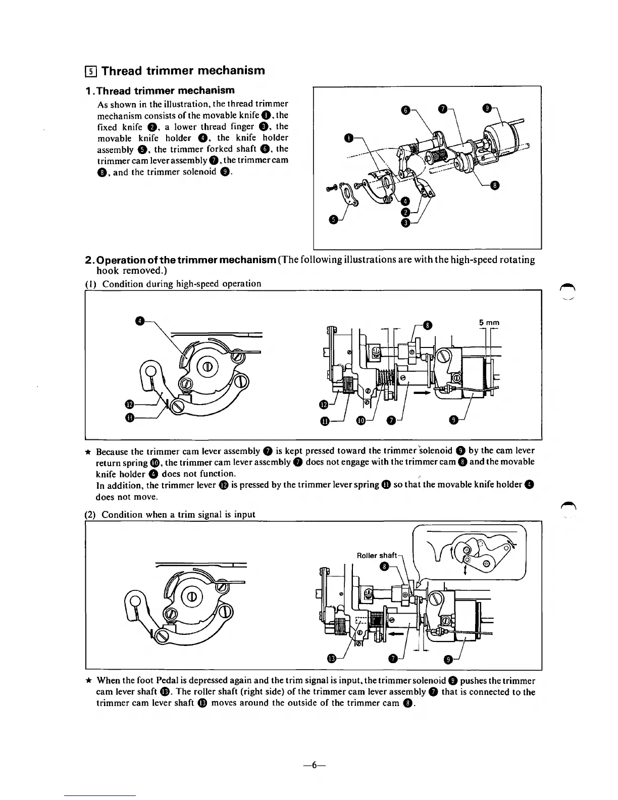
(}] Thread trimmer mechanism
1 . Thread trimmer mechanism
As shown
in
the illustration, the thread trimmer
mechanism consists
of
the movable knife
0,
the
fixed knife
0.
a lower thread finger
8.
the
movable knife holder
G. the knife holder
assembly
8.
the trimmer forked shaft
8.
the
trimmer cam lever assembly
8,
the trimmer
cam
0,
and
the trimmer solenoid
8.
2.
Operation of the trimmer mechanism(The following illustrations are with the high-speed rotating
hook
removed.)
(I)
Condition during high-speed operation
* Because the trimmer cam lever assembly 8
is
kept pressed toward the trimmer 'solenoid 8 by the cam lever
return spring
f),
the trimmer cam lever assembly 8 does not engage with the trimmer
cam
0
and
the movable
knife holder
8 does
not
function.
,.
In addition, the trimmer lever 8
is
pressed by the trimmer lever spring
CD
so
that
the movable knife holder 8
does not move.
(2) Condition when a trim signal
is
input
* When the foot Pedal
is
depressed again
and
the trim signal
is
input, the trimmer solenoid 8 pushes the trimmer
cam lever shaft
G).
The roller shaft (right side)
of
the trimmer
cam
lever assembly 8
that
is
connected
to
the
trimmer
cam
lever shaft
G)
moves
around
the outside
of
the trimmer
cam
0.
-6-