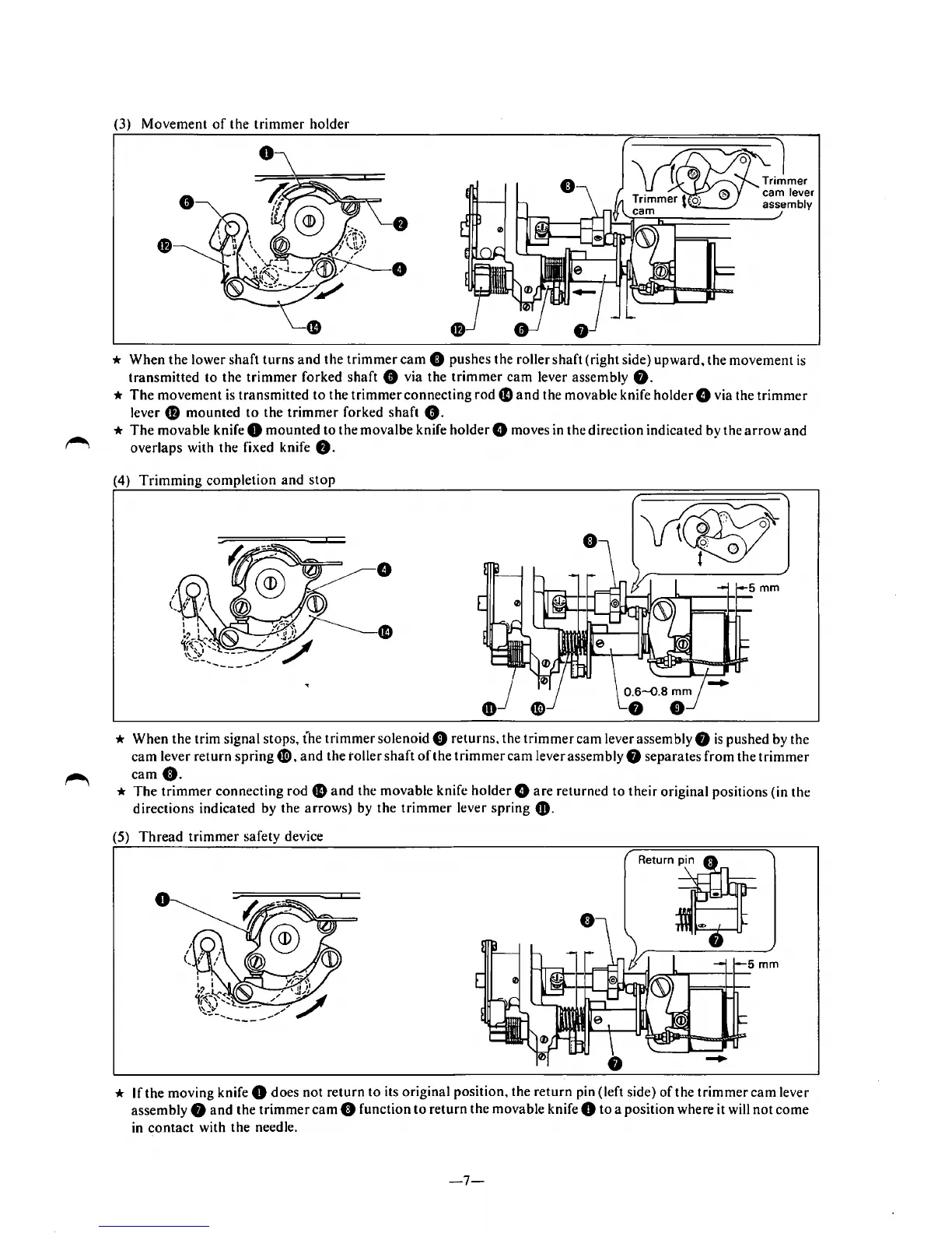
(3) Movement
of
the
trimmer
holder
*
When
the
lower shaft
turns
and
the
trimmer
cam
0 pushes the roller
shaft
(right side)
upward,
the
movement
is
transmitted
to
the
trimmer
forked
shaft
8 via the
trimmer
cam
lever assembly
8.
*
The
movement
is
transmitted
to
the
trimmer
connecting
rode
and
the movable knife
holder
8 via the
trimmer
lever 0
mounted
to
the
trimmer
forked
shaft
8.
*
The
movable knife 0
mounted
to the movalbe knife
holder
8 moves in the direction indicated by the
arrow
and
overlaps with the fixed knife
8.
(4)
Trimming
completion
and
stop
* When
the
trim signal stops, t'he
trimmer
solenoid 8 returns, the
trimmer
cam
lever assembly 8
is
pushed by the
cam
lever
return
spring
G),
and
the toller
shaft
oft
he
trimmer
cam
lever assembly 8 separates
from
the
trimmer
came.
*
The
trimmer
connecting rod
fD
and
the movable knife
holder
8
are
returned
to
their original positions (in
the
directions indicated by the
arrows)
by
the
trimmer
lever
spring
CD.
(5)
Thread
trimmer
safety device
0
* If the moving knife 0 does
not
return
to
its original position, the
return
pin (left side)
of
the
trimmer
cam
lever
assembly
8
and
the
trimmer
cam
8 function
to
return
the
movable knife 0
to
a position where it will
not
come
in
contact
with
the
needle.
-7-