~.
i
l
l
r
I
I
r
!
i
!
~
I
I
.
I
l
J
I
I
~
IT]
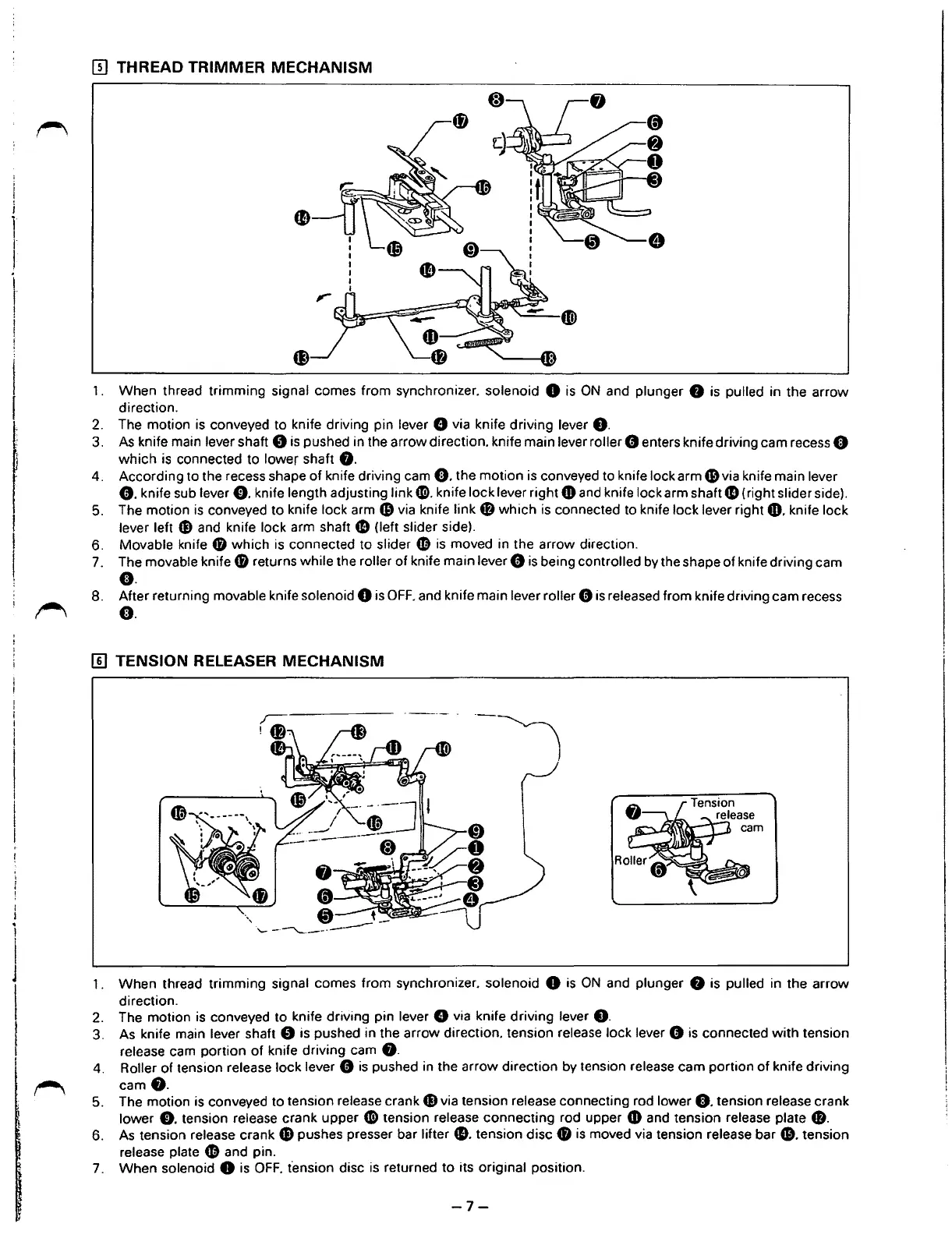
THREAD TRIMMER MECHANISM
1.
2.
3.
4.
5.
6.
7.
8.
When thread trimming signal comes from synchronizer. solenoid 8
is
ON
and plunger 8
is
pulled in the arrow
direction.
The motion
is
conveyed to knife driving pin lever 8 via knife driving lever
8.
As
knife main lever shaft 8
is
pushed in the arrow direction. knife main lever roller 8 enters knife driving cam recess e
which
is
connected to lower shaft
8.
According to the recess shape of knife driving cam
e.
the motion
is
conveyed to knife lock arm
6)
via knife main lever
8.
knife sub lever
0.
knife length adjusting link
CD.
knife lock lever right
4D
and knife lock arm shaft
G)
(right slider side).
The motion
is
conveyed to knife lock arm
6)
via knife link
4B
which
is
connected to knife lock lever right
49.
knife lock
lever left
G)
and knife lock arm shaft
G)
(left slider side).
Movable knife
0 which
is
connected to slider
fD
is
moved in the arrow direction.
The movable knife
0 returns while the roller of knife main lever 8
is
being controlled
by
the shape of knife driving cam
e.
After returning movable knife solenoid 8
is
OFF.
and knife main lever roller G
is
released from knife driving cam recess
e.
[[]
TENSION RELEASER MECHANISM
1 .
2.
3.
4.
5.
6.
7.
When thread trimming signal comes from synchronizer. solenoid 8
is
ON
and plunger 8 is pulled in the arrow
direction.
The motion
is
conveyed to knife driving pin lever 8 via knife driving lever
0.
As knife main lever shaft 8 is pushed in the arrow direction. tension release lock lever 0
is
connected
with
tension
release cam portion of knife driving cam
8.
Roller of tension release lock lever 8
is
pushed in the arrow direction by tension release cam portion
of
knife driving
cam8.
The motion is conveyed to tension release crank
G)
via tension release connecting rod lower
e.
tension release crank
lower
0.
tension release crank upper
CD
tension release connecting rod upper
4D
and tension release plate
8.
As
tension release crank
G)
pushes presser bar lifter
41).
tension disc 0 is moved via tension release bar
41.
tension
release plate
fD
and pin.
When solenoid
8
is
OFF.
t'ension disc
is
returned to its original position.
-7-
From the library of: Superior Sewing Machine & Supply LLC
 Loading...