l
I
I
J
J
I
I
[[]
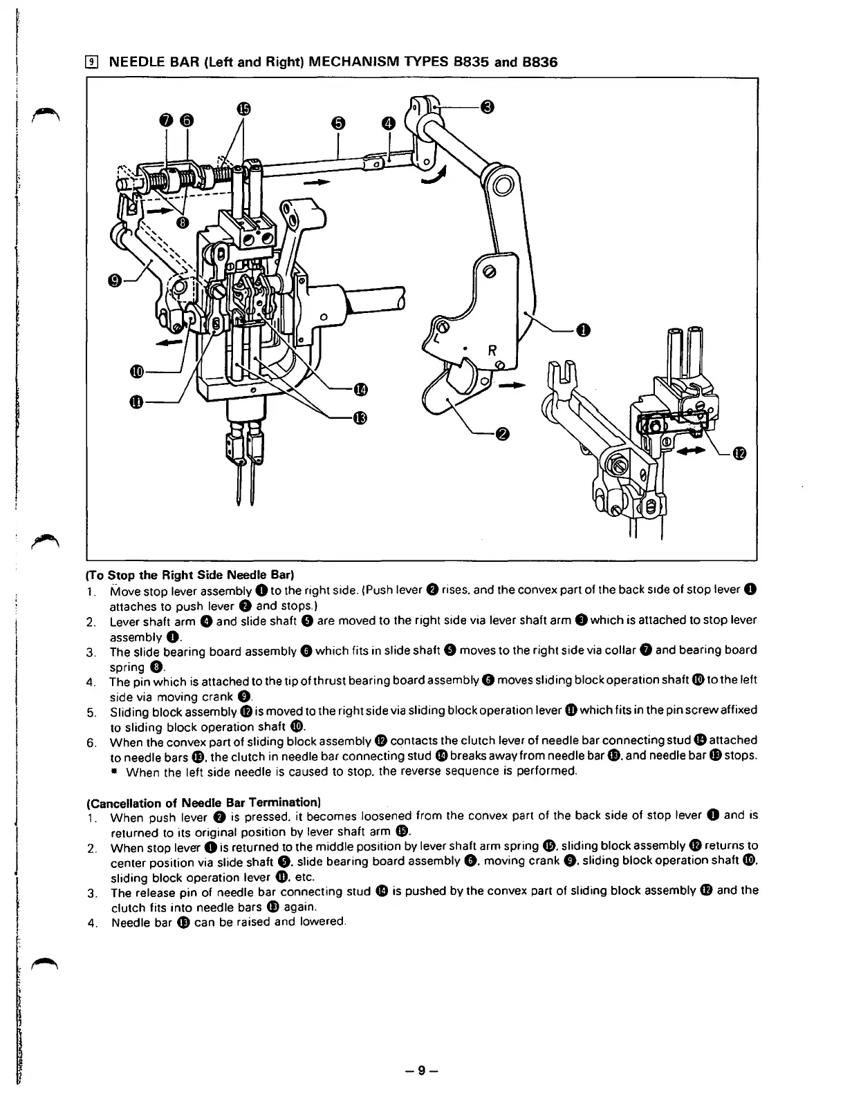
NEEDLE BAR
(left
and Right)
MECHANISM
TYPES
8835
and
8836
(To Stop the Right Side Needle Bar)
1.
Move stop lever assembly 0 to the right side. (Push lever
f)
rises. and the convex part of the back
s1de
of stop lever 0
attaches to push lever
f)
and stops.)
2.
Lever shaft arm 8 and slide shaft 0 are moved to the right side via lever shaft arm 8 which is attached to stop lever
assembly
O.
3.
The slide bearing board assembly 8 which fits in slide shaft 0 moves to the right side via collar 8 and bearing board
spring
0.
4. The pin which is attached to the tip of thrust bearing board assembly 8 moves sliding block operation shaft
G)
to the left
side via moving crank
0.
5.
Sliding block assembly
48
is moved to the right side via sliding block operation lever
CD
which fits in the pin screw affixed
to sliding block operation shaft
G).
6.
When the convex part
of
sliding block assembly
fB
contacts the clutch lever of needle bar connecting stud
41
attached
to needle bars
fl). the clutch in needle bar connecting stud
41
breaks away from needle
bar~.
and needle bar fl) stops.
• When the left side needle
is
caused to stop. the reverse sequence
is
performed.
(Cancellation
of
Needle Bar Termination)
1. When push lever
f)
is
pressed. it becomes loosened from the convex part
of
the back side
of
stop lever 0 and is
returned to its original position
by
lever shaft arm
CD.
2.
When stop lever 0 is returned to the middle position by lever shaft arm
spring&.
sliding block assembly
fB
returns
to
center position via slide shaft
0.
slide bearing board assembly
0.
moving crank
0.
sliding block operation shaft
G>.
sliding block operation lever
CD.
etc.
3. The
release pin of needle bar connecting stud
41
is
pushed by the convex part of sliding block assembly
CD
and the
clutch fits into needle bars fl) again.
4. Needle bar G) can
be
raised and lowered.
-9-
From the library of: Superior Sewing Machine & Supply LLC
 Loading...