Do you have a question about the Brother XR6060 and is the answer not in the manual?
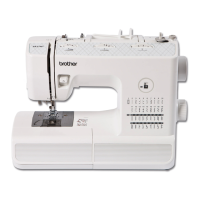
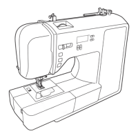
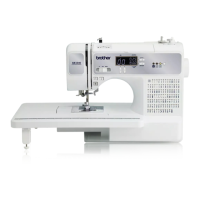
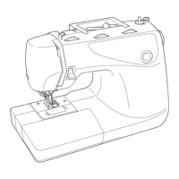
Diagram and overview of the sewing machine's primary mechanical components.
Explanation of the movement mechanisms for needle bar, thread take-up, and feed dog.
Diagrams illustrating the placement of electronic parts on the machine's covers.
Visual representation of the machine's electronic system interconnections.
Description of the functions of various electronic parts like buttons, sensors, and switches.
Instructions and diagrams for disassembling and reassembling the sewing machine's main components.
Procedures for removing and installing electrical components, motors, and power supply.
Detailed steps for disassembling and assembling the needle bar, presser, and upper shaft mechanisms.
Instructions for the disassembly and assembly of the sewing machine's feed mechanism.
Guidance on the disassembly and assembly of the bobbin winder mechanism.
Instructions for reattaching main machine parts after disassembly, with component diagrams.
Detailed procedures for disassembling specific main parts of the sewing machine.
Specific instructions for disassembling electrical components and motors.
Detailed procedures for disassembling the needle bar, presser, and upper shaft mechanisms.
Specific instructions for disassembling the bobbin winder mechanism.
Procedures for disassembling the feed and rotary modules of the sewing machine.
Detailed instructions for disassembling the needle-presser module.
Instructions for reassembling the sewing machine's main parts.
Procedures for reassembling electrical components and motors.
Instructions for reassembling the needle bar, presser, and upper shaft mechanisms.
Guidance on reassembling the bobbin winder mechanism.
Procedures for reassembling the feed and rotary modules.
Detailed instructions for reassembling the needle-presser module.
How to start, select modes, and operate test modes for adjustments.
Procedure to adjust the timing belt deflection to the specified 4-5mm.
Procedure to adjust the motor belt deflection to the specified 3-4mm.
Steps to adjust upper thread tension using a tension gauge to 0.32-0.37N.
Adjusting needle drop position for the left base line in the 'V' groove.
Adjusting the rotary hook unit's left/right position for proper needle drop.
Ensuring equal clearance between needle and outer rotary hook at base line.
Aligning needle's right edge with rotary hook point at specific needle bar height.
Setting needle eye to outer rotary hook point distance to 1.0-1.4mm.
Adjusting scarf-needle to hook point clearance to 0.2mm or less.
Setting hook edge to needle eye clearance to 0-0.1mm for proper threading.
Adjusting presser foot clearance and parallelism to the feed dog hole.
Adjusting forward feed length to be 0-10mm longer than backward feed length.
Adjusting bobbin winding for evenness and quantity (80-90% of diameter).
Setting BH lever eccentric shaft for correct switch activation based on clearance.
Centering the needle drop point within the presser foot hole.
Adjusting feed dog clearance and alignment with the needle plate.
Setting feed dog height from needle plate surface to 0.9-1.1mm at highest position.
Adjusting clearance between inner rotary hook and bracket spring to 2.3-2.5mm.
Adjusting the lower thread tension of the inner rotary hook to 0.1-0.12N.
List of error messages and their probable causes for electronic failures.
Flowcharts for diagnosing and resolving displayed error messages (F1-F4).
Troubleshooting steps when the sewing machine does not power on.
Diagnosing issues where pulse motors fail to return to their starting position.
Troubleshooting steps when patterns cannot be selected on the operation panel.
Diagnosing and resolving problems where the main motor does not rotate.
Troubleshooting unstable or slow main motor rotation and speed adjustment issues.
Diagnosing why patterns are not sewn correctly by checking mechanical and electrical components.
Troubleshooting issues with sewing button holes correctly, checking BH lever and switches.
Diagnosing why operation buttons on the panel are unresponsive.
Troubleshooting when the machine does not operate via the foot controller.
Diagnosing why the bobbin thread cannot be wound onto the bobbin.
Troubleshooting steps when the LED work light does not illuminate.
Diagnosing and resolving problems with the LCD screen display.
Troubleshooting steps when the machine's buzzer does not produce sound.
Guidance on routing and securing wires for the needle bar and presser modules.
Instructions for connecting wires to the power supply unit and main PCB.
Wiring procedures for components located in the front cover, including PCBs and lamps.
| Brand | Brother |
|---|---|
| Model | XR6060 |
| Category | Sewing Machine |
| Language | English |