126
SYSTEM ANALYSIS
IGNITION AND ELECTRICAL CIRCUITS
IGNITION AND
ELECTRICAL CIRCUITS
Following is a complete list of circuits required for
ignition output:
Stop Circuit
• Outboard running: black/yellow wire NOT
grounded (emergency stop switch lanyard in
place).
Battery
• Battery switched B+ input to power up EMM
• Battery B+ input to Start Assist Circuit (SAC) of
EMM
Stator Output Voltage
• Provides EMM J2 connector with A/C voltage:
Outboard cranking, typical range is 20-40 VAC
(AC output voltage is related to cranking RPM
);
outboard running approximately 55 VAC.
EMM
• Start Assist Circuit (SAC) of EMM converts bat-
tery voltage (12 V) to 30 V for system circuit
(55 V).
• Stator output to EMM provides voltage to
EMM’s internal power supply.
• EMM digital ground, battery grounds, ignition
grounds, and injector grounds must be func-
tional.
Crankshaft Position Sensor
• Provides EMM with input.
• Outboard cranking speed exceeds 75 RPM and
a steady CPS signal is generated.
Alternator Output/System Voltage
• System voltage from EMM (white/red) provides
55 VDC to the oil injection pump, the fuel injec-
tors, and the ignition module of EMM.
Capacitor
• Connected to 55 V circuit (white/red) to stabilize
current on 55 V circuit.
• Negative terminal of capacitor must be
grounded.
Ignition Primary Voltage
• Output from EMM.
• EMM provides -200 VDC ± 10 V output to
orange ignition primary wires during cranking.
IMPORTANT: Peak reading voltmeters must be
set to “NEG” and “500” settings to measure igni-
tion voltage.
Ignition Coil
• EMM provides input to primary winding of coil.
• Output from ignition coil secondary winding and
high tension spark plug wire.
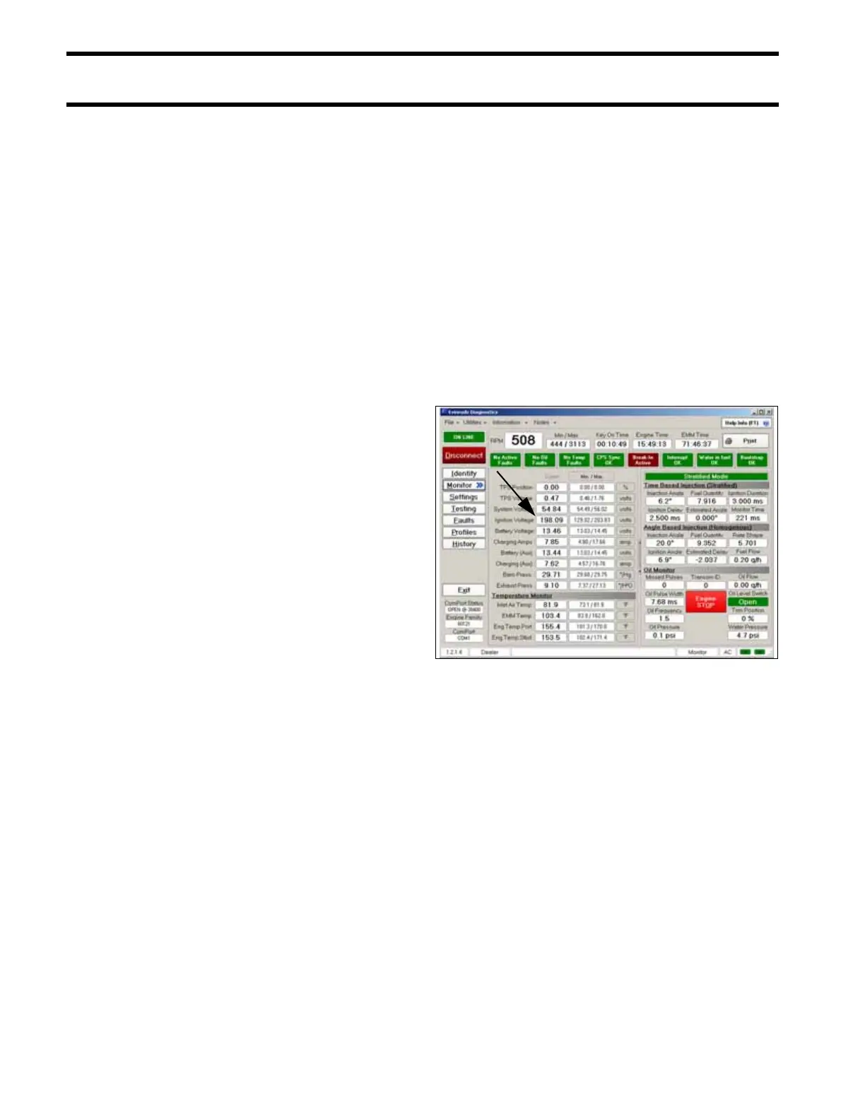
Engine Monitor Screen, Ignition Voltage 005141




 To Next Page