221
POWERHEAD
POWERHEAD INSTALLATION
10
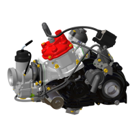
Place the shift rod in the shift rod lever. Install the
retaining pin and washer. Tighten pin to a torque
of 60 to 84 in. lbs. (7 to 9.5 N·m).
Check shift linkage adjustment. Refer to Shift
Linkage Adjustment on p. 224.
IMPORTANT: Make sure the gearcase shifts
completely into both forward and reverse and that
propeller shaft spins freely in neutral.
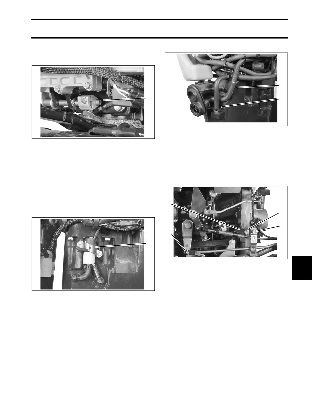
Apply Nut Lock to threads of exhaust water valve
screws and tighten to a torque of 60 to 84 in. lbs.
(7 to 9.5 N.m).
Connect cooling water hoses to exhaust housing.
Connect the power trim connectors and exhaust
water valve connector (60, 65). Secure cables in
clamps.
ROPE START MODELS
Install throttle cable and tiller shift rod.
Refer to Throttle Cable Adjustment on p. 273, or
Throttle Cable Adjustment on p. 284.
Install recoil starter ratchet and housing on out-
board. Refer to RECOIL STARTER INSTALLA-
1. Shift rod screw 002171
1. Exhaust water valve 004293
1. Overboard indicator hose
2. Drain hose
004298
1. Cable anchor
2. Anchor screw
3. Cable retainer
4. Shift rod retainer
006526m