62
OUTBOARD RIGGING
EVINRUDE E-TEC 60° V MODELS 115–200 HP
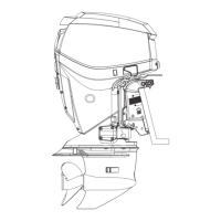
Route the harness under the front of the EMM and
around the port side of the powerhead. Secure
with tie straps.
Use an I-Command Ignition and Trim Harness to
connect the outboard to the key switch and trim/tilt
control. Seal unused SystemCheck connector
with 6-Pin Connector Seal, P/N 586076.
If connecting to an existing Deutsch-style I-Com-
mand network, connect the purple wires between
the I-Command Ignition and Trim Harness and the
I-Command Engine Interface Cable. This connec-
tion supplies power to the network when the key
switch is on. Newer, quick connect-style networks
do not use this connection.
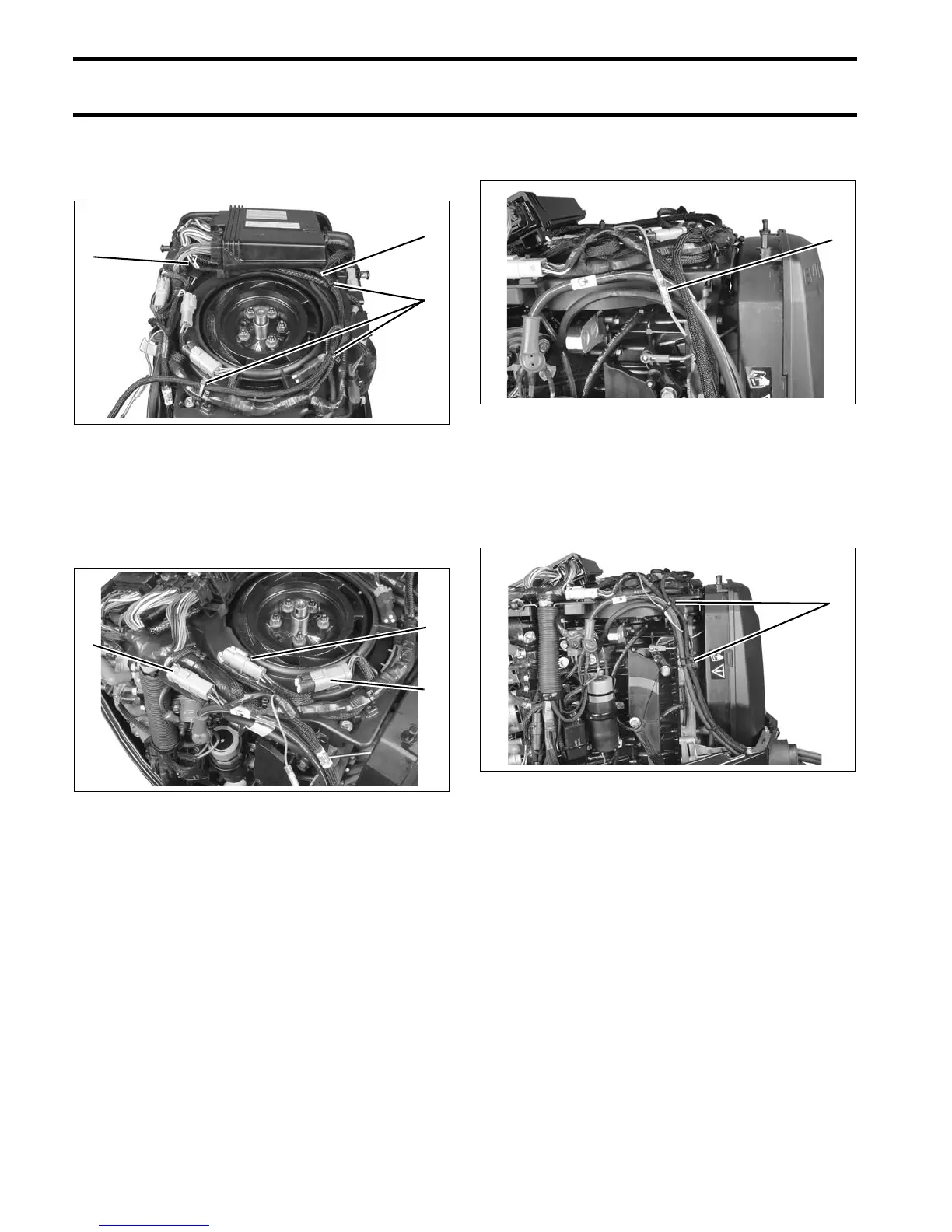
Route the harnesses around the starboard side of
the powerhead along the same path as the battery
cables.
Secure all cables with tie-straps.
For an I-Command oil level display, an accessory
CANbus oil level sender must be installed in the
oil tank. Connect the sender to the I-Command
network. Refer to the I-Command Digital Net-
work Guide, P/N 355008.
1. Harness routing
2. Tie straps
005268
1. I-Command Ignition connector
2. Trim/Tilt connector
3. SystemCheck connector (with seal)
005266
1. Network power supply connector 005269
1. Anchor points 005270