4.4) After engine start
m WARNING
Non-compliance can result in serious injuries or death!
Do not start the engine if any person is near the engine.
Warming up
period
Step Step Description Procedure
1 Check engine instru-
ments (Warning Indi-
cators and
Operational Limits)
and ensure compli-
ance with the operat-
ing limits while step 2
to 4.
HIC A: If a 12 V voltage drop
between Terminal 2 and Termi-
nal 8 at 916 i Type A, or at 916 i
Type C24 Terminal A and D
(permanent or oscillating) is de-
tected, shut OFF engine and
perform troubleshooting.
HIC B: If a 12 V voltage drop
between Terminal 2 and Termi-
nal 10 at 916 i Type A, or at 916
i Type C24 Terminal A and D
(permanent or oscillating) is de-
tected, shut OFF engine and
perform troubleshooting.
Display CAN A/B: Check and
ensure compliance with opera-
tional limits.
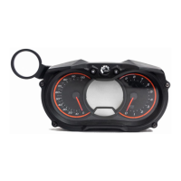
Example (Symbolic) Warning Lamp A: Check
Warning Lamp B: Check
Pilot Display: Check
2 Set Throttle Valve as
required.
Set linearized throttle position in
a way that the engine runs at
approx. 2000 rpm for approx. 2
minutes.
Example (Symbolic) Set Throttle.
3 Set Throttle Valve as
required.
Set linearized throttle position in
a way that the engine runs on
approx. 2500 rpm until oil tem-
perature reaches 50 °C (120 °
F).
Example (Symbolic) Set Throttle.
4 Reduce Throttle
Valve as required.
Set linearized throttle position
so that the engine runs at idle.
Example (Symbolic) Reduce Throttle.
Page 4-12
December 01 2023
BRP-Rotax Effectivity: 916 i A / C24
Edition 0 / Rev. 1

 Loading...
