Lane and Ignition
check
During the Lane and Ignition check Engine Speed must always
show plausible values no matter if one or both lanes are active.
Otherwise maintenance is required.
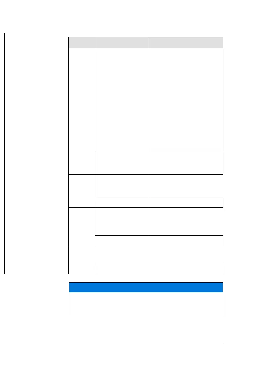
Step Step Description Procedure
1 Check engine instru-
ments (Warning Indi-
cators and
Operational Limits)
and ensure compli-
ance with the operat-
ing limits while step 2
to 11.
HIC A: If a 12 V voltage drop
between Terminal 2 and Termi-
nal 8 at 916 i Type A, or at 916 i
Type C24 Terminal A and D
(permanent or oscillating) is de-
tected, shut OFF engine and
perform troubleshooting.
HIC B: If a 12 V voltage drop
between Terminal 2 and Termi-
nal 10 at 916 i Type A, or at 916
i Type C24 Terminal A and D
(permanent or oscillating) is de-
tected, shut OFF engine and
perform troubleshooting.
Display CAN A/B: Check and
ensure compliance with opera-
tional limits.
Example (Symbolic) Warning Lamp A: Check
Warning Lamp B: Check
Pilot Display: Check
2 Set Throttle Valve as
required.
Set linearized throttle position
so that engine speed is approx
2500 rpm.
Example (Symbolic) Set Throttle
3 Deactivate ECU Lane
A
HIC A: Disconnect Terminal 1
and Terminal 7 at 916 i Type A,
or at 916 i Type C24 Terminal N
and P, to turn OFF ECU Lane A.
Example (Symbolic) Lane select Switch A: OFF
4 Observe engine
speed
Display CAN A/B; Check engine
speed.
Example (Symbolic) Pilot Display: Check
NOTICE
Engine speed should not drop/increase more than 250 rpm. If the
fuel pressure is not within the limits, the cause must be determined.
The engine must not be put into service until the problem is rectified.
Page 4-14
December 01 2023
BRP-Rotax Effectivity: 916 i A / C24
Edition 0 / Rev. 1

 Loading...


