Effectivity: 916 i A / C24
Edition 0 / Rev. 1
BRP-Rotax Page 4-19
December 01 2023
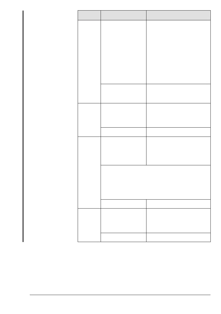
Step Step Description Procedure
compliance with the
operating limits.
detected, shut OFF engine and
perform troubleshooting.
HIC B: If a 12 V voltage drop
between Terminal 2 and Termi-
nal 10 at 916 i Type A, or at 916
i Type C24 Terminal A and D
(permanent or oscillating) is de-
tected, shut OFF engine and
perform troubleshooting.
Display CAN A/B: Check and
ensure compliance with opera-
tional limits.
Example (Symbolic) Warning Lamp A: Check
Warning Lamp B: Check
Pilot Display: Check
11 Activate ECU Lane B HIC B: Connect Terminal 1 and
Terminal 9 at 916 i Type A, or at
916 i Type C24 Terminal N and
P to power ECU Lane B.
Example (Symbolic) Lane select Switch B: ON
12 Await Warning Indi-
cator B to extinguish
and note how long
this takes.
HIC A: 12 V voltage drop be-
tween Terminal 2 and Terminal
10 at 916 i Type A, or at 916 i
Type C24 Terminal A and D for
3 seconds.
NOTE
After the voltage drop between Terminal 2 and
Terminal 10 changes back to 0 V wait approx. 3
seconds until continuing with the next step.
Example (Symbolic) Warning Lamp B: Check
13 Reduce Throttle
Valve as required
Set linearized throttle position
to reach an engine speed of
2000 rpm and continue with
Fuel pump check.
Example (Symbolic) Set Throttle
Fuel pump check
Verify that both fuel pumps are working and that no loss of
power or irregular running occurs during deactivation of one fuel
pump. The limits for fuel pressure must not be exceeded. Air-
craft Manufacturer is responsible for defining a procedure for
checking the fuel pumps.

 Loading...


