4.6) Engine shut-off
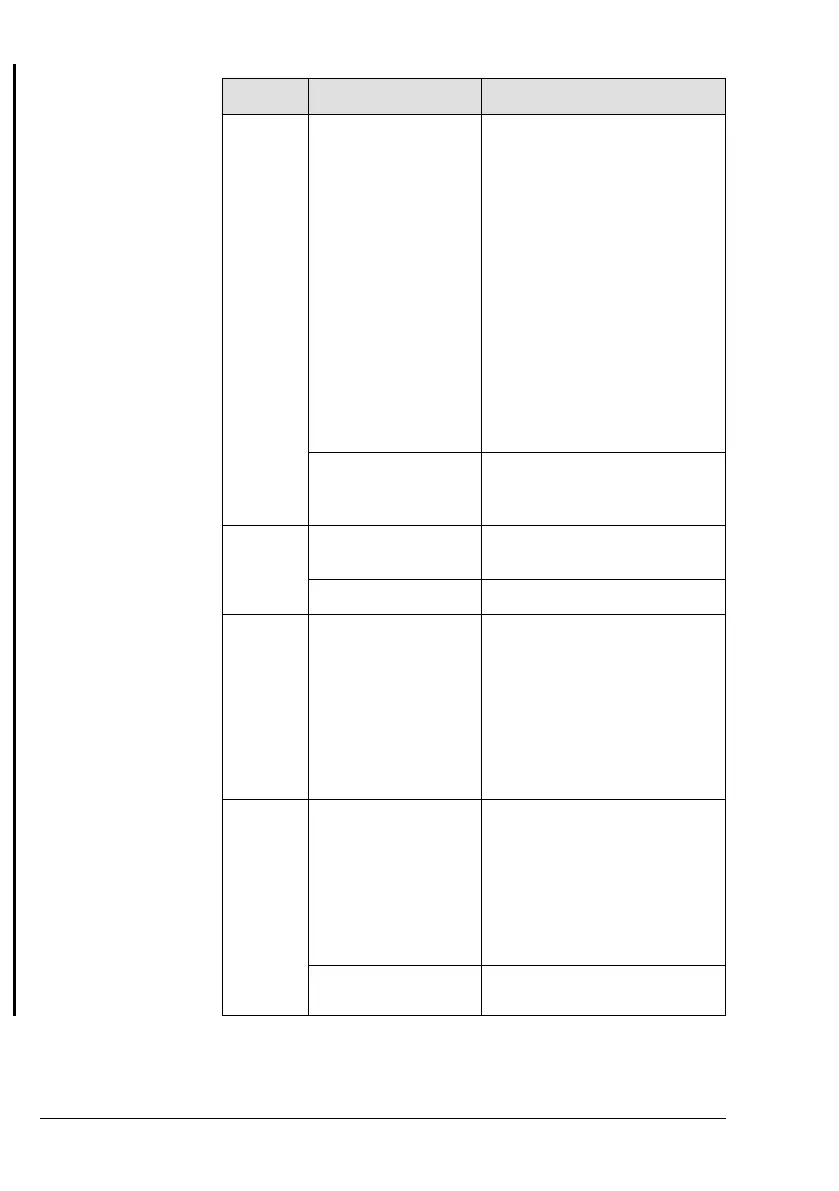
Step Step Description Procedure
1 Check the engine in-
struments (Warning
Indicators and Opera-
tional Limits) and en-
sure compliance with
the operating limits
while step 2 to 5.
HIC A: If a 12 V voltage drop
between Terminal 2 and Termi-
nal 8 at 916 i Type A, or at 916 i
Type C24 Terminal A and D
(permanent or oscillating) is de-
tected, shut OFF engine and
perform troubleshooting.
HIC B: If a 12 V voltage drop
between Terminal 2 and Termi-
nal 10 at 916 i Type A, or at 916
i Type C24 Terminal A and D
(permanent or oscillating) is de-
tected, shut OFF engine and
perform troubleshooting.
Display CAN A/B: Check and
ensure compliance with opera-
tional limits
Example (Symbolic) Warning Lamp A: Check
Warning Lamp B: Check
Pilot Display: Check
2 Reduce Throttle
valve as required.
Set linearized throttle position
so that the engine runs on idle.
Example (Symbolic) Reduce Throttle
3 Await cooling down
phase.
Normally the cooling down of
the engine during descending
and taxiing will be sufficient to
allow the engine to be shut off
as soon as the aircraft stopped.
At increased operating temper-
atures make an engine cooling
run of at least minimum 2
minutes.
4 Deactivate ECU HIC A: Disconnect Terminal 1
and Terminal 7 at 916 i Type A,
or at 916 i Type C24 Terminal N
and P to turn OFF ECU Lane A
HIC B: Disconnect Terminal 1
and Terminal 9 at 916 i Type A,
or at 916 i Type C24 Terminal N
and P to turn OFF ECU Lane B.
Example (Symbolic) Lane select Switch A: OFF
Lane select Switch B: OFF
Page 4-20
December 01 2023
BRP-Rotax Effectivity: 916 i A / C24
Edition 0 / Rev. 1

 Loading...


