7.6) Air intake system and Boost pressure control
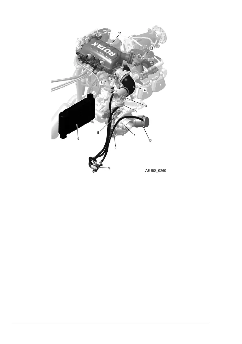
Figure 13: Air intake system
1 Airfilter connection 2
Turbo charger to
intercooler
3
Intercooler to pop off
valve
4
Pop off valve to throttle
body
5
Turbocharger
6 Intercooler
7
Pop off valve
8
Throttle body
9 Pressure control valve
10
Actuator assy.
(Wastegate)
11 Airbox
12
Intake manifold
Air flow
The compressor side of the turbocharger sucks air through the
airfilter and pushes it thru the Intercooler into the airbox. The
pressure in the airbox is controlled by the Throttle. From the air-
box the compressed air moves thru the intake manifolds into
the four cylinders.
Page 7-16
December 01 2023
BRP-Rotax Effectivity: 916 i A / C24
Edition 0 / Rev. 1

 Loading...


