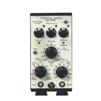
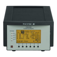
Do you have a question about the BRUEL & KJAER 2636 and is the answer not in the manual?
Verifies basic operational parameters like sensitivity and frequency response.
Interprets fault codes indicated by LEDs and meters for troubleshooting.
Assesses amplifier stage linearity across specified gain ranges.
Evaluates the linearity of the detector circuit with varying input levels.
Tests various detector modes including Peak, Max Peak, Decay, and Hold.
Verifies the correct operation of all implemented filter circuits.
Measures and assesses instrument noise floor characteristics.
Details the instrument's built-in self-test program for diagnostic checks.
Checks front panel controls during the self-test procedure.
Verifies instrument calibration using the internal reference generator.
Checks amplifier linearity by adjusting gain steps during self-test.
General precautions for performing self-tests and checks.
Lists specific voltage checks required on the Mother Board ZH 0196.
Procedure for adjusting the off-set for the Input/Output Amplifier.
Adjusting input and output sections for proper frequency response.
Adjusting settings to check and manage overload conditions.
Adjusting the reference oscillator for accurate measurements.
Checking filter curves against specified attenuation values.
Adjusting the rectifier circuit for proper DC output.
Adjusting DC level and gain for logarithmic output.
Testing and adjusting meter amplifier and log/lin converter.
Checking peak detector and setting detector output modes.
Describes the Intel 8748 CPU and PROM 2716 for program storage.
Explains the multiplexed data/address bus usage for CPU communication.
Procedure for adjusting P2 (Gain Adj) for processor bits.
Lists pin mnemonics for the ZD 0241 connector.
Lists pin mnemonics for the ZD 0240 connector.
Lists pin mnemonics for the ZD 0240 P-connector.
Lists pin mnemonics for the ZD 0242 L-connector.
Exploded view illustrating the assembly of mechanical parts.
Shows the physical layout of components on the A/D Converter board.
Lists all components used in the A/D Converter circuit.
Shows the physical layout of components on the Processor ZD 0241 board.
Lists all components used in the Processor ZD 0241 circuit.
Shows the physical layout of components on the IEC-Interface ZD 0242 board.
Lists all components used in the IEC-Interface ZD 0242 circuit.
Visual representation of component placement on the Input Amplifier board.
Detailed list of components with values for the Input Amplifier.
Schematic of Amplifier 1, 2, and 3 stages.
Diagram of reference oscillator and gain control circuits.
Visual representation of component placement on the Output Amplifier board.
Detailed list of components with values for the Output Amplifier.
Schematic of amplifier stages and detector buffer.
Diagram of reference oscillator and overload indicator circuits.
Visual representation of component placement on the Amplifier Control board.
Lists components for Amplifier Control and Meter Circuit.
Schematic for gain and input control sections.
Diagram of output section gain and LED indicators.
Shows the physical placement of components on the Power Supply board.
Lists all components used in the Power Supply circuit.
Visual representation of component placement on the Mother Board.
Detailed list of components with values for the Mother Board.
Visual representation of component placement on the Detector and Filter Control board.
Detailed list of components with values for Detector and Filter Control.
Schematic of input buffer and filter sections.
Diagram of detector function and interface control circuits.
Visual representation of component placement on the Detector I board.
Detailed list of components with values for the Detector I board.
Schematic of rectifier and log converter stages.
Diagram of integrator and peak detector circuits.
Visual representation of component placement on the Detector II board.
Detailed list of components with values for the Detector II board.
Schematic of impulse detector and meter amplifier stages.
Diagram of peak detector and recorder amplifier circuits.
Visual representation of component placement on the Filter Circuit board.
Detailed list of components with values for the Filter Circuit board.
Schematic of input buffer and filter sections.
Diagram of filter selection and control logic.
| Brand | BRUEL & KJAER |
|---|---|
| Model | 2636 |
| Category | Amplifier |
| Language | English |
