Do you have a question about the BRUEL & KJAER 2626 and is the answer not in the manual?
Explains the need for a preamplifier and the advantages of the 2626 amplifier.
Explains the purpose and design of the charge amplifier for independence from cable length.
Details the basic circuit and working principle of a charge amplifier.
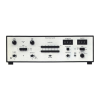
Describes the controls and indicators on the front panel of the 2626.
Details the sockets and controls on the rear panel of the 2626.
Explains the input connections and considerations for low frequency measurements.
Describes the direct and transformer outputs and their characteristics.
Specifies the power input voltage and consumption of the amplifier.
Explains the function of the reset button after overload conditions.
Discusses using the amplifier in servo-loop systems and associated precautions.
Provides guidance for performing low frequency measurements, considering pyroelectric effects.
Offers advice on minimizing hum and noise for accurate measurements.
Details how to calculate noise referred to the input.
Explains the input amplifier stage and its characteristics.
Describes the transducer sensitivity setting and conditioning resistors.
Details the low-pass and high-pass filter circuits and their characteristics.
Explains the output amplifier stage, direct vs. transformer output.
Describes the overload and -20 dB indicators.
Explains the power supply input voltage and internal regulation.
Discusses frequency response influenced by loading and output voltages.
Presents the spectrum of inherent noise and refers to calculation methods.
Explains phase shift determined by filters and its calculation.
Describes the setup for calibrating accelerometers using the 2626.
Explains the popularity and application of wide band random vibration testing.
Describes using the 2626 for mechanical impedance measurements.
Explains the suitability of the 2626 for correlation measurements.
| Frequency Range | 2 Hz to 200 kHz |
|---|---|
| Gain Settings | 10 dB steps |
| Output Impedance | 50 Ω |
| Gain | 60 dB |
| Input Impedance | 1 MΩ |



 Loading...