Betriebsanleitung NLG5 User’s manual NLG5
12.2003-NLG5xx_179_ab Nr25 33 / 47
6.2.5 PG1..3 (Protected Ground)
Pins 8, 14, 15
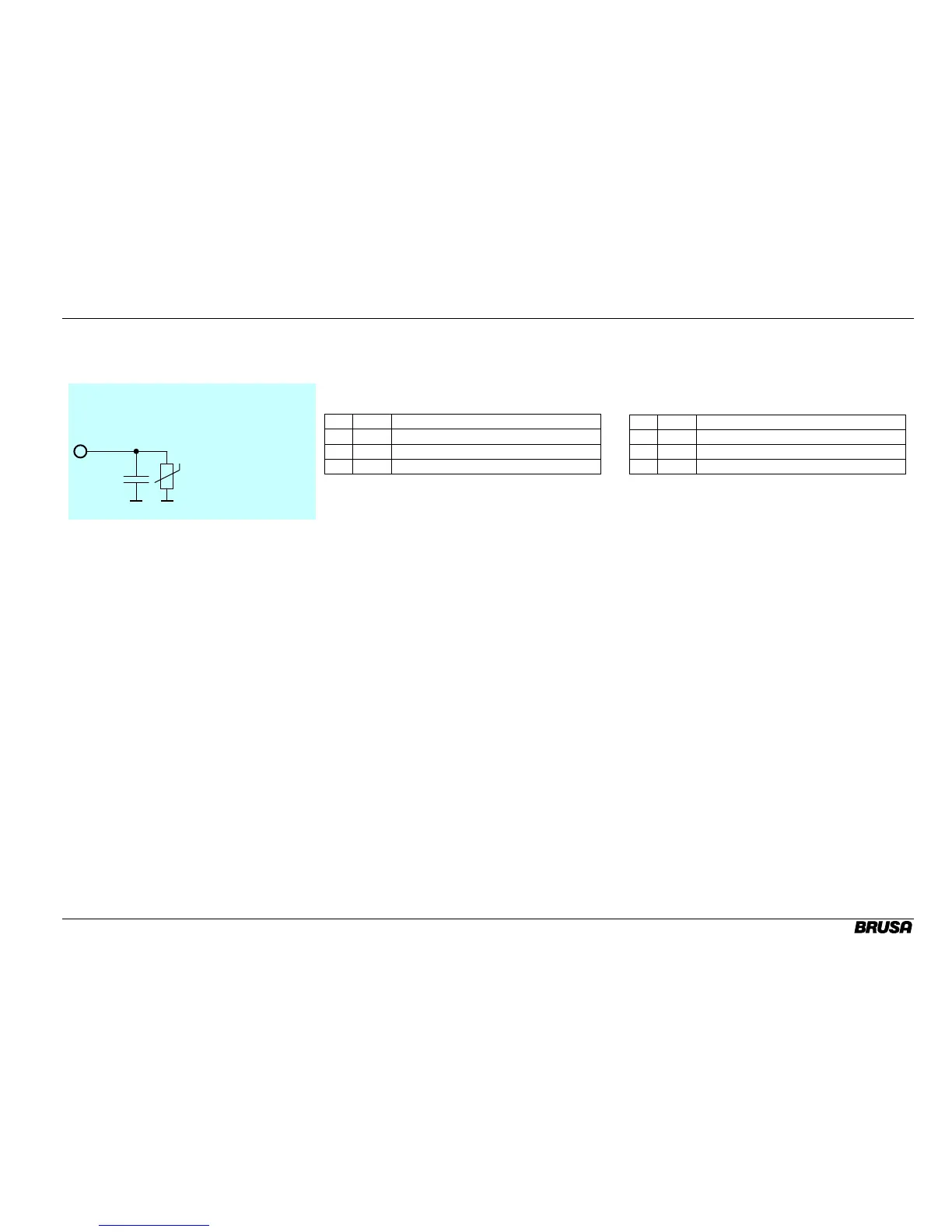
Interne Beschaltung
Internal Circuit
470
PG1,PG2,PG3
(8,14,15)
PTC
max.0.75A
R=1Ω
Zur Vereinfachung der externen Verdrahtung wurden drei
zusätzliche Masse-Anschlüsse vorgesehen. Diese sind
über je eine PTC-Sicherung mit der Versorgungs-Masse
GND verbunden.
Folgende Zuordnung wird empfohlen:
Nr. Abk. Funktion
8
PG1 Analog Masse (für Pins 20 - 23)
14
PG2 Reserve Masse
15
PG3 RS232 Masse (9-pol D-Sub: Pin 5)
In order to simplify external wiring, there are 3 additional
ground connectors. They are connected to the supply's
ground (GND) by a PTC fuse.
We recommend to assign the pins as follows:
Pin Abbr. Function
8
PG1 Analog Ground (for pins 20 - 23)
14
PG2 Reserve Ground
15
PG3 RS232 Ground (9 pin D-Sub: pin 5)


 To Next Page