Do you have a question about the Brusa NLG5 and is the answer not in the manual?
General warnings, handling high DC voltages, heat production, and flammable materials.
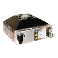
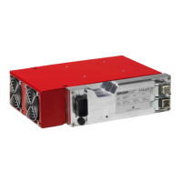
Lists essential parts for a ready-to-use charger and optional accessories.
Diagram identifying main components and detailing module units (AC/DC, Bypass, Control).
Explains control modes (Auto, Booster, CAN) and the Master-Booster concept.
Details the different operating modes of the charger.
Automatic charging based on programmed profiles with distinct charging sections.
Unit acts as a booster to increase the charging power of a master charger.
Control via CAN bus, enabling sophisticated custom control via a BMS.
Information on automatic power limitation features.
Automatic limitation of charging power to protect the charger from overload.
Limits mains power input and defines maximum output current based on voltage and modules.
Power reduction due to high temperatures to prevent overheating.
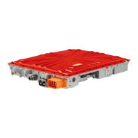
Specific model for on-board charging in electric vehicles.
Unit used to increase charging power of single-phase chargers.
Instructions for displaying and monitoring charger operation.
Steps to configure Hyperterminal for connecting to the NLG5.
How to start the monitoring program and view main characteristics.
Detailed pin assignments for output and input sockets.
Guidelines for mounting and installing the charger unit.
Step-by-step guide for installing the charger unit in a vehicle.
Pinout diagram and list of functions for the 23-pole signal connector.
Internal circuit descriptions for GND (Pin 1) and AUX (Pin 2).
Internal circuit description for the PON (Pin 3) and its functions.
Internal circuit and fault indication for FLT, DO2, DO3, DO4 (Pins 4-7).
Internal circuit description for protected ground pins PG1, PG2, PG3 (Pins 8, 14, 15).
Properties and CAN messages for the CAN interface (Pins 9, 10).
RS232 interface functions for connecting to a PC (Pins 11, 12).
Functions of PRO pin (Pin 13) for firmware and Digital Inputs (Pins 16-19) for profile control.
Connection of temperature sensors (NTC) and configuration (Pins 20-22).
Function of the Power Indicator pin (Pin 23) for mains current limitation.
Overview of power specifications, protection means, and fulfilled standards.
Features like power multiplying, booster function, CAN interface, and PC connectivity.
Physical dimensions, weight, temperature range, and IP rating of the unit.
Details on charger types, power ranges, voltage ranges, cooling, and modes.
Overview of different power classes (3.3 kW, 6.7 kW, 10 kW).
Available charge voltage ranges and their corresponding current limits.
Description of cooling options (Top, Side, Water).
Available operating modes (Automatic, CAN, Booster).
| Brand | Brusa |
|---|---|
| Model | NLG5 |
| Category | Battery Charger |
| Language | English |